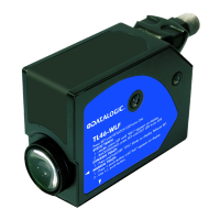
S100 SERIES IO-Link
Instruction Manual
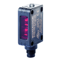
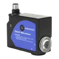
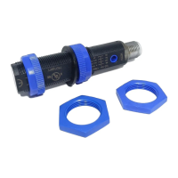
CONTROLS
OUTPUT LED – Yellow
The yellow LED indicates the output status.
Please refer to “Settings” for procedure indications during
acquisition or setting phases.
INSTALLATION
The sensor can be positioned by means
of the two housing’s threaded holes (M3)
using two screws (M3x12 or longer or
M2.5 passing screw, 0.4 Nm maximum
tightening torque) with washers or by
mean of the two rear holes using two
M3 passing screw, 0.4Nm maximum
tightening torque.
Various orientable xing brackets to
ease the sensor positioning are available
(please refer to the accessories listed in
the catalogue).
During installation of transparent models
(S100-T10) refer to the diagram below
for proper alignment between sensor and
reector.
CONNECTIONS
DIMENSIONS
TECHNICAL DATA
Power Supply 10 ... 30 VDC (Class 2 UL508) (reverse polarity protected)
Ripple 10% max.
Current consumption (output current
excluded)
30 mA max.
Output PNP, NPN or Push-Pull (short-circuit protection)
Output current 100 mA max. (total for both outputs), 100 mA max. (for single output)
Output saturation voltage 2 V max.
Input Pin 2 can be congured as an input through IO-Link. If so, it cannot be kept disconnected
Response time M10/T10: 1 ms; B10: 500 µs
Switching frequency M10/T10: 500 Hz; B10: 1kHz
Indicators Output LED (yellow)
Operating temperature -25 °C ... +55 °C
Storage temperature -40 °C ... +70 °C
Operating distance (typical values)
B10: 0.01 ... 4.5 m (on R2 reector Ø 48mm)
M10: 30…200 mm (on White 90%)
T10: 0.1…2 m (on R2 reector Ø 48mm)
Optical axis deviation (max.) 5° mod. T10
Distance object detection
M10: 10…200 mm (on White 90%)
T10: 0.1…2 m (on trasparent object)
Dierence on White 90% / Gray 18% M10: < 23% at 200 mm
Hysteresis on White 90% M10: < 20 mm at 200 mm
Emission type
Red LED (632 nm) mod.B10, Infrared LED (860 nm) mod.T10/B10
Exempt Risk Group (RG0) for IEC 62471
Ambient light rejection according to EN 60947-5-2
Vibration 0.5 mm amplitude, 10 … 55 Hz frequency, for every axis (EN60068-2-6)
Shock resistance 11 ms (30 G) 6 shock for every axis (EN60068-2-27)
Housing ABS body / indicators cover PMMA
Lenses PC lens / window PMMA
Mechanical protection IP67
Connections M8 4-pole connector
Weight 10 g.
SETTINGS
The N.C. output can be congured through IO-Link as a REMOTE input (M10/T10) or as
a L/D input. Set the input through IO-Link and follow the instructions. The input cannot be
kept disconnected.
LIGHT/DARK INPUT (S100-B10)
The L/D input allows the operator to select the DARK/LIGHT operating mode as follows:
- pin 2 connected to: 0V = DARK mode, +Vcc = LIGHT mode.
Alignment S100-B10
Position the sensor and reector on opposite sides. Find the points where the yellow LED
(OUT) is switched ON and OFF in both vertical and horizontal positions and x the sensor in
the centre between these points.
REMOTE input (external Teach-in) S100… M10/T10
The REMOTE input sets the background suppression operating distance for M10 and the
reading sensitivity for T10 using two dierent acquisition procedures:
S100-M10
Object acquisition (to be used in case of absence of the background)
1. Place the target opposite the sensor at the maximum distance required;
2. Connect the REMOTE wire to + VDC for 1 second. The OUT LED changes its status once.
If the object is out of range the sensor fails the acquisition and the OUT LED blinking. To
return at normal operation, connect the REMOTE + VDC for 100ms.
Acquisition for background suppression
1. Place the sensor in front of the background within the maximum operating distance.
2. Connect the REMOTE wire to +VDC for 3 seconds.The OUT LED changes its status
twice. If the object is out of range the sensor fails the acquisition and the OUT LED
blinking. To return at normal operation, connect the REMOTE + VDC for 100ms.
S100-T10
Reector standard acquisition
1. Position the reector in front of the sensor at the required distance (within the operating
range).
2. Connect the REMOTE wire to +VDC for 1 second. The OUT LED changes its status once.
If the reector is outside the operation range, the sensor fails the acquisition and the OUT
LED blinks. To go back to the condition before the acquisition, connect the REMOTE wire to
+VDC for at least 100 msec.
Reector acquisition at maximum sensitivity
This procedure allows to obtain a more precise alignment between sensor and reector, in
particular for longer reading distances:
1. Connect the REMOTE wire to +VDC for 3 seconds. The OUT LED changes its status
twice: the sensor is at maximum sensitivity.
2. Position the reector in front of the sensor (within the operating range), vertically and
horizontally determine the OUT LED switching on and o points, and secure the reector
in the centre between such points.
3. Connect the REMOTE wire to +VDC for 1 second. The OUT LED changes its status once.
LIGHT/DARK selection (S100…M10/T10)
To change the operating DARK/LIGHT mode connect the REMOTE wire to +VDC for 7
seconds until the LED OUT changes its status three times.
The sensor blinks and switches the operating mode (LIGHT → DARK, DARK → LIGHT)
and saves it in memory.
R1
Ø 23
mm
R2
Ø 48
mm
R3
18x54
mm
R4
47x47
mm
R5
Ø 75
mm
R6
36x55
mm
RT3970
60x40
mm
B10 0.02...2
0.01...4.5
0.01...3
0.01...4.5 0.01...5.5
0.01...4 0.05...1.8
T10 0.1...1 0.1...2 0.1...1 0.1...2 0.1...2.5 0.1...2 0.1...0.8
TAB.1: Operating distances for B10 and T10 models (m)
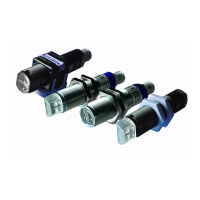
AVAILABLE REFLECTORS
Sensors are NOT safety devices, and MUST NOT be used in the safety
control of the machines where installed.
Datalogic S.r.l.
Via S. Vitalino 13 - 40012 Calderara di Reno - Italy
Tel: +39 051 3147011 - Fax: +39 051 3147205 - www.datalogic.com
Helpful links at www.datalogic.com: Contact Us, Terms and Conditions, Support.
The warranty period for this product is 36 months. See General Terms and Conditions of
Sales for further details.
For information about the disposal of Waste Electrical and Electronic Equipment
(WEEE), please refer to the website at www.datalogic.com.
© 2020 Datalogic S.p.A. and/or its aliates - ALL RIGHTS RESERVED. - Without limiting
the rights under copyright, no part of this documentation may be reproduced, stored
in or introduced into a retrieval system, or transmitted in any form or by any means, or
for any purpose, without the express written permission of Datalogic S.p.A. and/or its
aliates. Datalogic and the Datalogic logo are registered trademarks of Datalogic S.p.A.
in many countries, including the U.S.A. and the E.U. All other trademarks and brands are
property of their respective owners. Datalogic reserves the right to make modications and
improvements without prior notication.
821006941 Rev. B
Dimensions in mm