Getting Started Guide 51
3
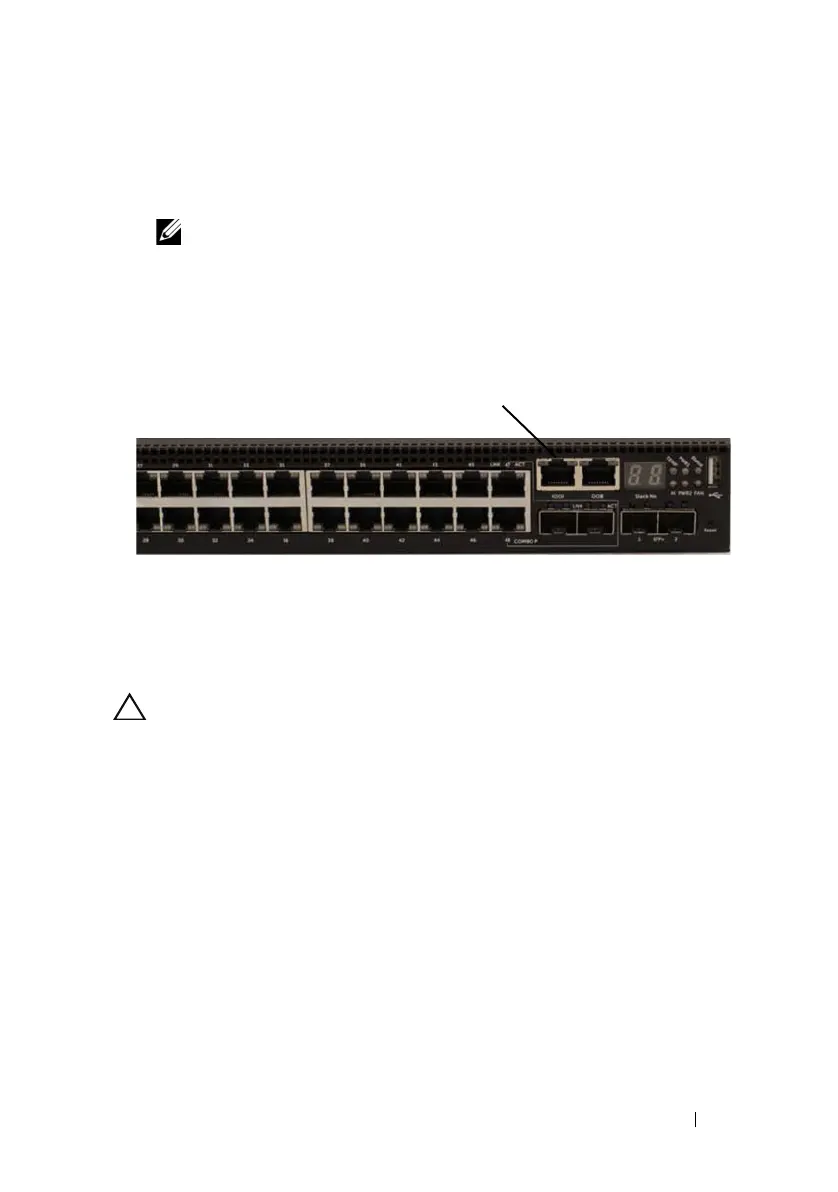
Connect the RJ-45 connector on the cable directly to the switch console
port. The Dell Networking console port is located on the right side of the
front panel and is labeled with a
|O|O|
symbol, as shown in Figure 1-25.
NOTE: Serial console access to the stack manager is available from any
serial port via the local CLI. Only one serial console session at a time is
supported.
Figure 1-25. N3048 Console Port Location
The RJ-45 port to the right of the console port is for out-of-band Ethernet
management.
Connecting a N30xx Switch to a Power Source
CAUTION: Read the safety information in the Safety and Regulatory Information
manual as well as the safety information for other switches that connect to or
support the switch.
The N30xx switches have two FRU power supplies for redundant or load-
sharing operation.
AC and DC Power Connection
1
Make sure that the switch console port is connected to a VT100 terminal
or VT100 terminal emulator via the RJ-45 to DB-9 female cable.
2
Using a 5-foot (1.5 m) standard power cable with safety ground connected,
connect the power cable to the AC main receptacle located on the back
panel (see Figure 1-26 on page 52).
3
Connect the power cable to a grounded AC outlet.
 Loading...