11 Dell EMC Networking with Isilon Front-End Deployment and Best Practices Guide | version 1.0
4 Leaf-spine overview
The connections between leaf and spine switches can be layer 2 (switched) or layer 3 (routed). The terms
“layer 3 topology” and “layer 2 topology” in this guide refer to these connections. In both topologies,
downstream connections to servers, storage and other endpoint devices within the racks are layer 2 and
connections to external networks are layer 3.
The following concepts apply to layer 2 and layer 3 leaf-spine topologies:
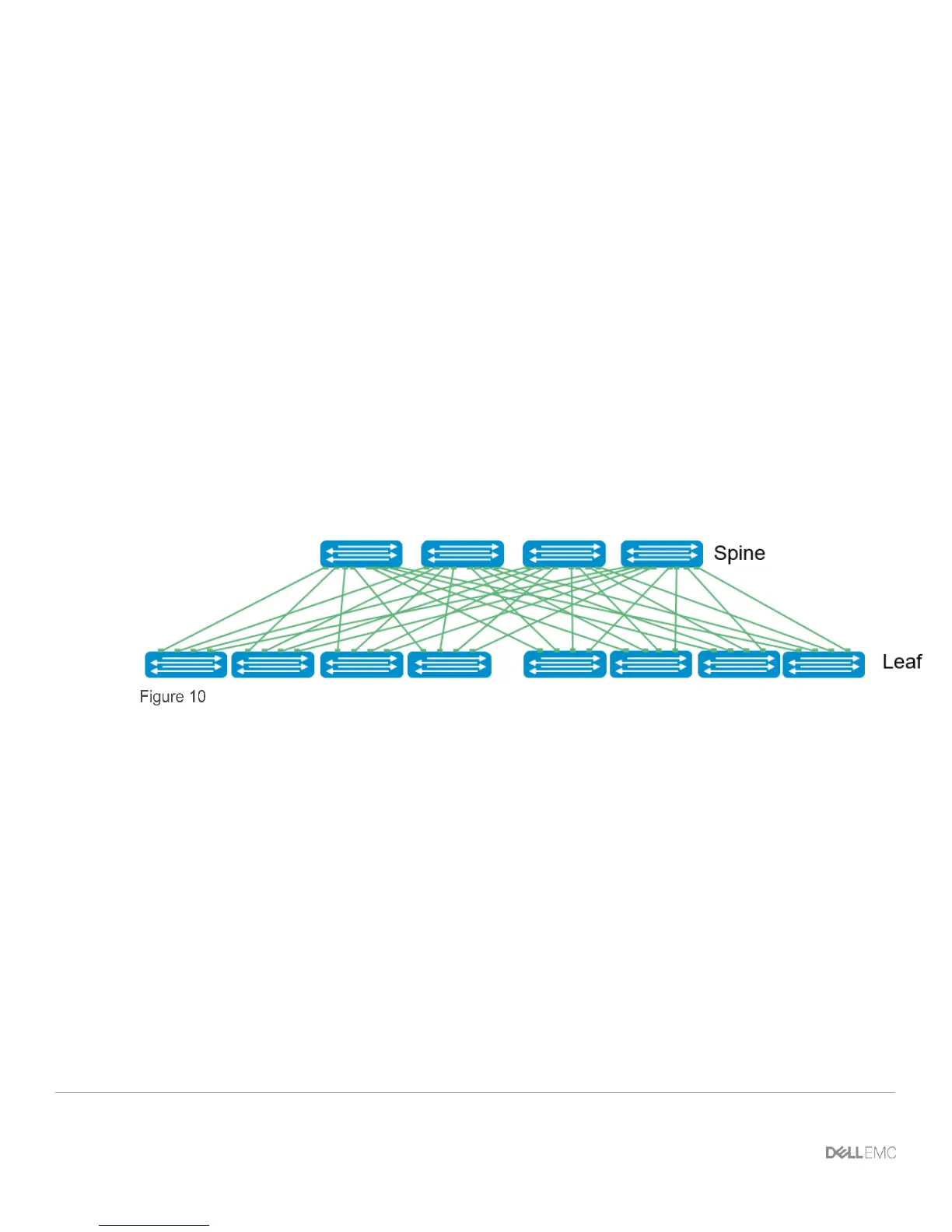
• Each leaf switch connects to every spine switch in the topology.
• Servers, storage arrays, edge routers and similar devices always connect to leaf switches, never to
spines.
The layer 2 and layer 3 topologies each use two leaf switches at the top of each rack configured as a Virtual
Link Trunking (VLT) pair. VLT allows all connections to be active while also providing fault tolerance. As
administrators add racks to the data center, two leaf switches configured for VLT are added to each new rack.
The total number of leaf-spine connections is equal to the number of leaf switches multiplied by the number of
spine switches. The bandwidth of the fabric may be increased by adding connections between the leaf and
spine layer as long as the spine layer has the capacity for the additional connections.
Leaf-Spine architecture
4.1 Design considerations
There are many different options regarding the selection of the correct topology that will best fit the needs of
the data center. In this section, the different protocols, topologies, and best practices will be covered. The
main differentiation will be whether the L2/L3 boundary is located at the spine layer or at the leaf layer. When
compared to a layer 3 topology, a layer 2 topology is generally less complex but has some limitations that
must be considered. These include:
• For each VLAN, the layer 2 topology creates one large broadcast domain across the fabric. The layer
3 topology has the benefit of containing broadcast domains to each rack.
• The layer 2 topology is limited to 4094 VLANs across the fabric. The layer 3 topology allows up to
4094 VLANs per rack.
• The layer 2 topology is limited to two physical switches at the spine layer (configured as VLT peers).
In a layer 3 topology, additional spines may be added as needed to provide additional paths and
bandwidth. Therefore, a layer 3 topology is more scalable and is better suited for very large networks.
 Loading...