14 15
MAINTENANCE
OTHER RECOMMENDED MAINTENANCE
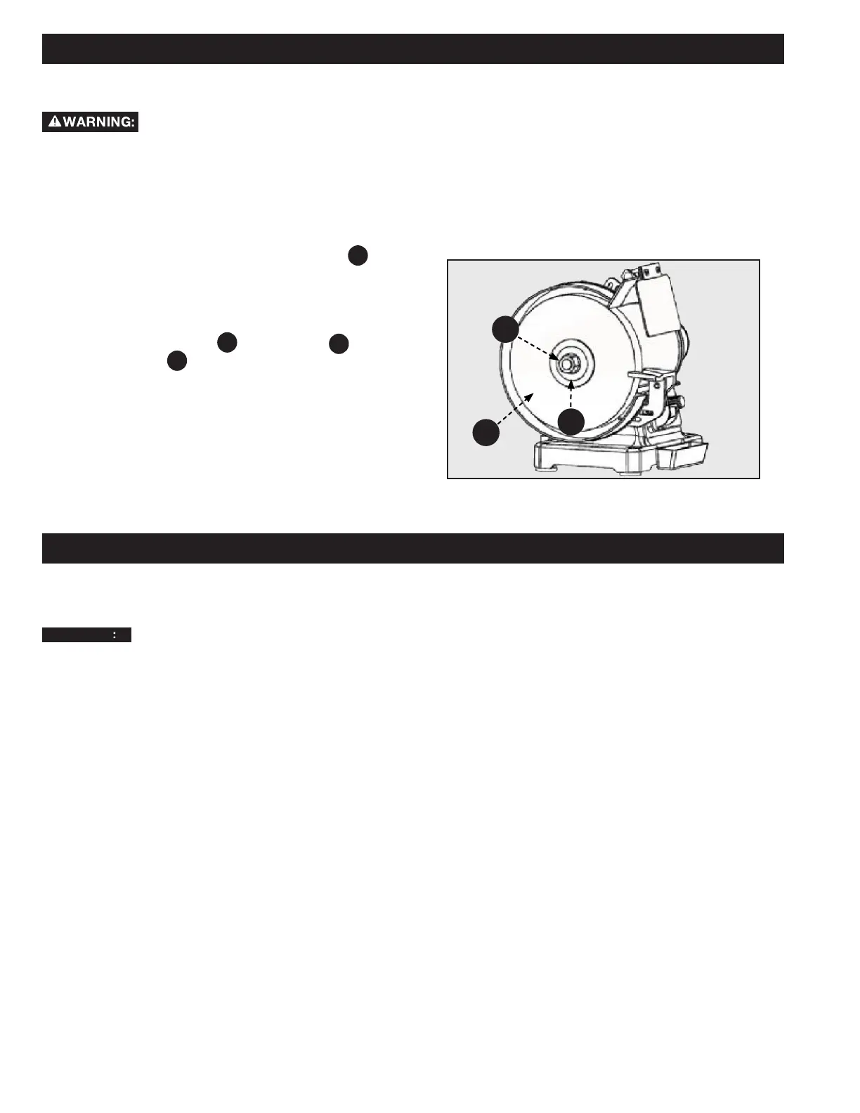
REPLACING OR CHANGING GRINDING WHEELS
Disconnect the machine from the power
source.
For steps 1-4, refer to Figures 4 & 5 on page 11:
1. Remove the (2) screws and the lower locking knob and
carriage bolt that secures the tool rest supports. These
secur the outer face of the wheel guard to the tool frame.
2. Remove the guard.
3. Using a 25mm wrench, loosen the arbor nut
A
while
using the other hand to keep the wheel from moving.
NOTE: To loosen the arbor nut on the right side rotate it
counterclockwise. To loosen the arbor nut on the left side rotate
it clockwise.
4. Remove the arbor nut
A
, wheel ange
B
, and old
grinding wheel
C
. See Figure 9.
5. Place the new grinding wheel on the arbor.
NOTE: Grinding wheels for the 23-196 must be 3/4 inch wide
while grinding wheels for the 23-197 must be 1 inch wide.
1. Periodically blow out all air passages with dry compressed
air. All plastic parts should be cleaned with a soft damp
cloth.
NEVER use solvents to clean plastic parts.
They could possibly dissolve or otherwise damage the material.
2. Periodically inspect the tightness of the arbor nuts.
3. Periodically check tightness on all other hardware and
listen for any unusual vibrations while you work as these
may be a sign of loose hardware.
Figure 9
6. Place the ange on the arbor and thread the arbor nut on
the arbor tighten the arbor nut as tightly as you can by
hand.
7. Replace the wheel guard and secure with the (2) screws,
carriage bolt, lower locking knob, and tool rest support
previously removed in step 1.
A
B
C
 Loading...