19
TRACKING THE BLADE
IMPORTANT: Before tracking the blade, confirm that
the blade guides and blade support bearings are clear of
the blade.
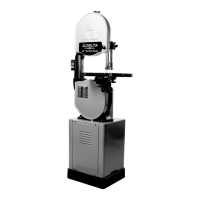
After applying tension to the blade, rotate the wheels
slowly forward by hand and observe the blade’s
movement. The blade (A) Fig. 31 should travel in the
center of the upper tire. If the blade creeps toward the
front edge, loosen the wing nut (B) Fig. 32 and turn the
thumb screw (C) clockwise. This action draws the blade
toward the center of the tire. If the blade creeps toward
the back edge, turn the thumb screw in the opposite
direction. Adjust the thumb screw (C) Fig. 32 only a
fraction of a turn each time.
Never track the blade while the
machine is running.
After the blade is tracking in the center of the tires,
tighten the wing nut (B) Fig. 32.
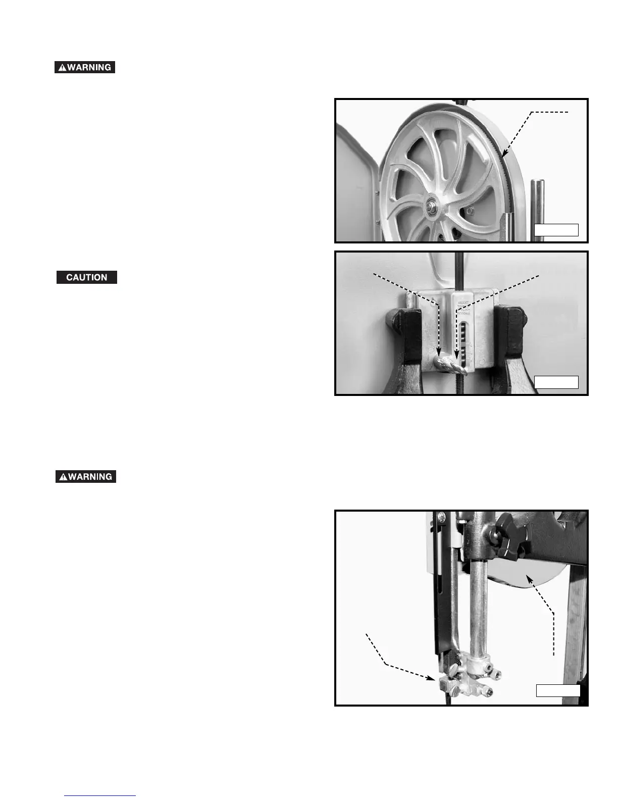
VERTICAL ADJUSTMENT OF THE UPPER BLADE GUIDE ASSEMBLY
To adjust the blade guides and bearings:
Set the upper blade guide assembly (A) Fig. 33 as close
as possible to the top surface of the workpiece. Loosen
the lock knob (B) and move the guide assembly (A) to
the desired position.
A
B
C
B
A
DISCONNECT MACHINE FROM POWER SOURCE!
Fig. 31
Fig. 32
Fig. 33
DISCONNECT MACHINE FROM POWER SOURCE!
 Loading...