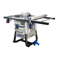
Fig. 7
Fig. 10Fig. 9
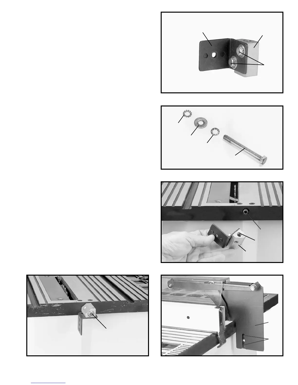
Fig. 8
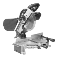
Fig. 6
ASSEMBLING
BLADE GUARD AND SPLIT-
TER ASSEMBLY
1. DISCONNECT THE SAW FROM THE POWER
SOURCE.
2. IMPORTANT: THE BLADE GUARD AND SPLITTER
ASSEMBLY MUST BE PROPERLY ALIGNED TO THE
SAW BLADE IN ORDER TO PREVENT KICKBACK.
3. Position the blade 90 degrees to the table and lock in
place.
4. Fasten the splitter support bracket (A) Fig. 9, to split-
ter bracket (B) using two 1/2 inch-long screws (C) which
were removed from splitter bracket (B) earlier, and two
1/4 inch external tooth lockwashers as shown. NOTE:
Do not completely tighten screws (C) at this time.
5. Locate the 2-1/4" long hex head screw (G) Fig. 7, and
assemble the internal tooth lockwasher (O), flat washer
(P) and external tooth lockwasher (R) onto screw (G).
6. Position recessed end (E) Fig. 8, of splitter bracket (B)
against end of pivot rod (F) and fasten in place using the
2-1/4" long hex head screw (G) Fig. 9, internal tooth
lockwasher, flat washer and external tooth lockwasher
which were assembled to screw (G) in STEP 5. NOTE:
Do not completely tighten screws (C) at this time.
7. Position the splitter (H) Fig. 10, on the splitter support
bracket as shown, making certain the two protrusions (K)
on the splitter support bracket are inside the slot of
splitter (H).
A
B
C
R
P
O
G
F
E
G
B
K
H
7
 Loading...