6
ASSEMBLY INSTRUCTIONS
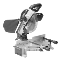
Fig. 3A
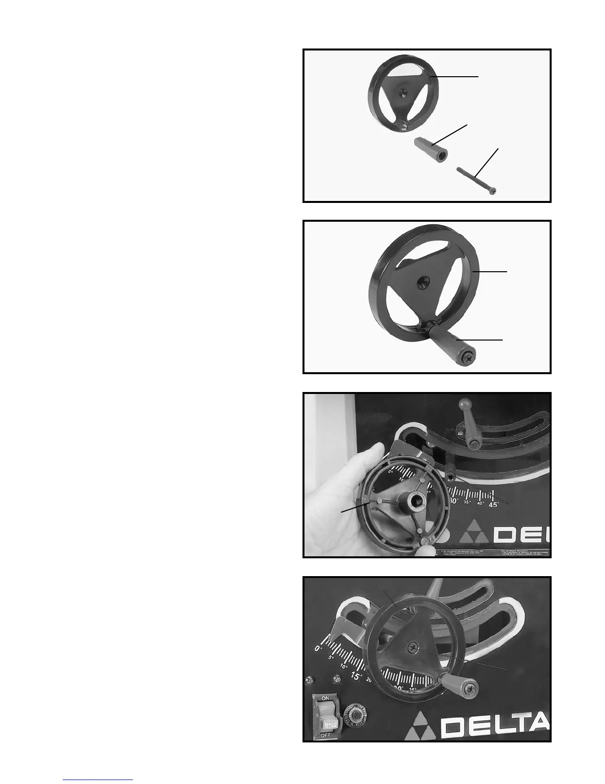
Fig. 3B
Fig. 4
Fig. 5
4. Fasten handwheel (A) Fig. 5, to shaft using a M6 x
12mm screw (7) Fig. 2A.
ASSEMBLING BLADE
RAISING AND LOWERING
HANDWHEEL
1. Insert M6 x 55 screw (9) Fig. 2A, through handle (E)
Fig. 3A, and assemble handle (E) to handwheel (A) by
threading screw (D) clockwise into handwheel.
2. Fig. 3B, illustrates the handle (E) assembled to hand-
wheel (A).
3. Assemble handwheel (A) Fig. 4, to shaft (B) making
sure the flat on inside of handwheel lines up with flat on
shaft.
D
E
A
A
E
7
A
A
B
 Loading...