8
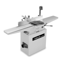
Fig. 3
16. Stand with Pre-Wired Switch
17. Dust Chute
18. V-Belt
19. Pulley
20. 3/8-16x2" Hex Head Screw (3)
21. M8x1.25x55mm Hex Socket Head Screw (4)
22. M8x1.25x25mm Hex Socket Head Screw (2)
23. M8x1.25x20mm Hex Socket Head Screw (2)
24. M8x1.25x16mm Hex Socket Head Screw (2)
25. 5/16-18x1" Hex Head Screw (1)
26. #10-16x1/2" Sheet Metal Screw (4)
27. 3/8" Flat Washer (6)
28. 11/32" Flat Washer (1)
29. M8 Flat Washer (10)
30. 3/8" Lockwasher (3)
31. M8.1 Lockwasher (10)
32. 5/16" Lockwasher (1)
33. M14x2 Hex Nut (1)
34. 3/8-16" Hex Nut (3)
35. 5/16-18 Hex Nut (1)
36. Key
16
17
18
19
20
21
22
23
24
25
26
27
28
29
30
31
32
34
35
36
ASSEMBLY
FOR YOUR OWN SAFETY, DO NOT CONNECT THE MACHINE TO THE POWER SOURCE UNTIL
THE MACHINE IS COMPLETELY ASSEMBLED AND YOU READ AND UNDERSTAND THE ENTIRE
INSTRUCTION MANUAL.
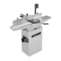
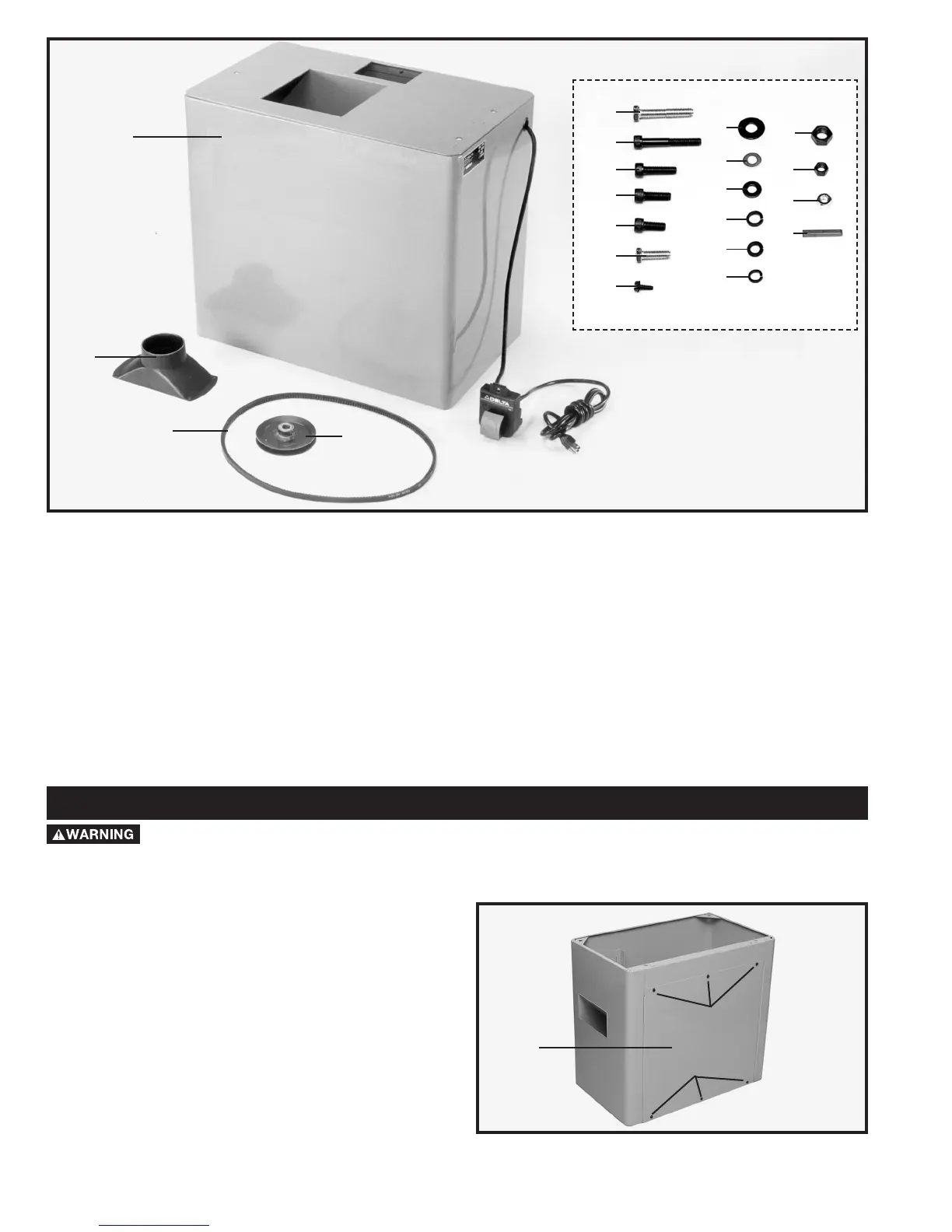
Fig. 4
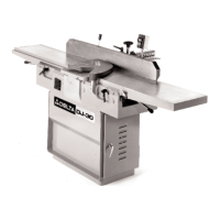
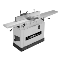
JOINTER TO STAND
Your Jointer stand (A) Fig. 4, is shipped with the motor
and switch completely wired.
NOTE: THE MOTOR IS BOLTED TO THE TOP OF THE
STAND AND MUST BE ATTACHED TO THE MOTOR
MOUNTING BRACKETS.
1. Remove the six screws (C) Fig. 4. Then remove back
panel (E) from the stand.
33
C
C
E
 Loading...