Chapter 11 DeviceNet Master Scanner Module AS01DNET-A
11-81
1
11.5.4.4. Connecting AS01DNET (RTU) to the Network
To configure AS01DNET (RTU) successfully and make it work normally in the network, the following steps should be
taken for the setup.
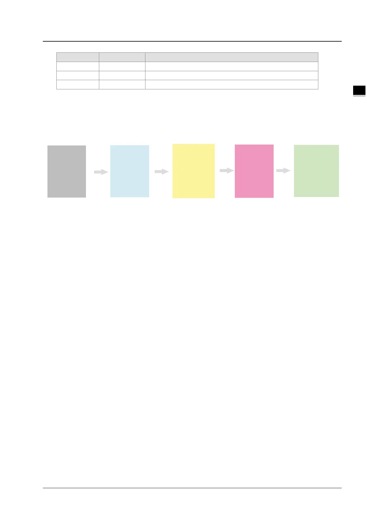
Ha rdwa re
Wiri ng
On li n e Scan
Configurati on
Down load
Mo ni tor & C he ck
Configurati on
Setting
Hardware wiring
During hardware wiring, notice that the standard cable should be used and two terminal resistors of 121Ω should be
connected respectively to the two ends of the main line in the DeviceNet network. The node IDs of all nodes in the network
bus can not be repeated and their baud rates should be consistent.
Online scan
The online scan consists of two parts: scanning online network nodes and scanning I/O modules of AS01DNET (RTU).
Before the scan, make sure that the communication channel selected is proper and the communication setup is normal in
the communication manager COMMGR.
Configuration setting
The configuration setting includes the master configuration and AS01DNET (RTU) configuration settings. The master
configuration contains the master scanner module setting (configuration of master) and the scan list configuration setting.
AS01DNET (RTU) configuration contains AS01DNET (RTU) setting and other I/O modules setting.
Configuration Download
Configuration download consists of master configuration download and AS01DNET (RTU) configuration download. During
the master configuration download, the seven-segment displayer of AS01DNET (RTU) shows 80 and its node ID alternately.
During the AS01DNET (RTU) configuration download, the seven-segment displayer of AS01DNET (RTU) shows 83 and
its node ID alternately.
Monitor and Check
After the configuration is downloaded, check if AS01DNET (RTU) works normally. If AS01DNET (RTU) works normally, the
digital displayers of the master and AS01DNET (RTU) show their own node IDs and MS and NS indicators are ON in green.
 Loading...