Chapter 9 Serial Communication Module AS00SCM
9- 37
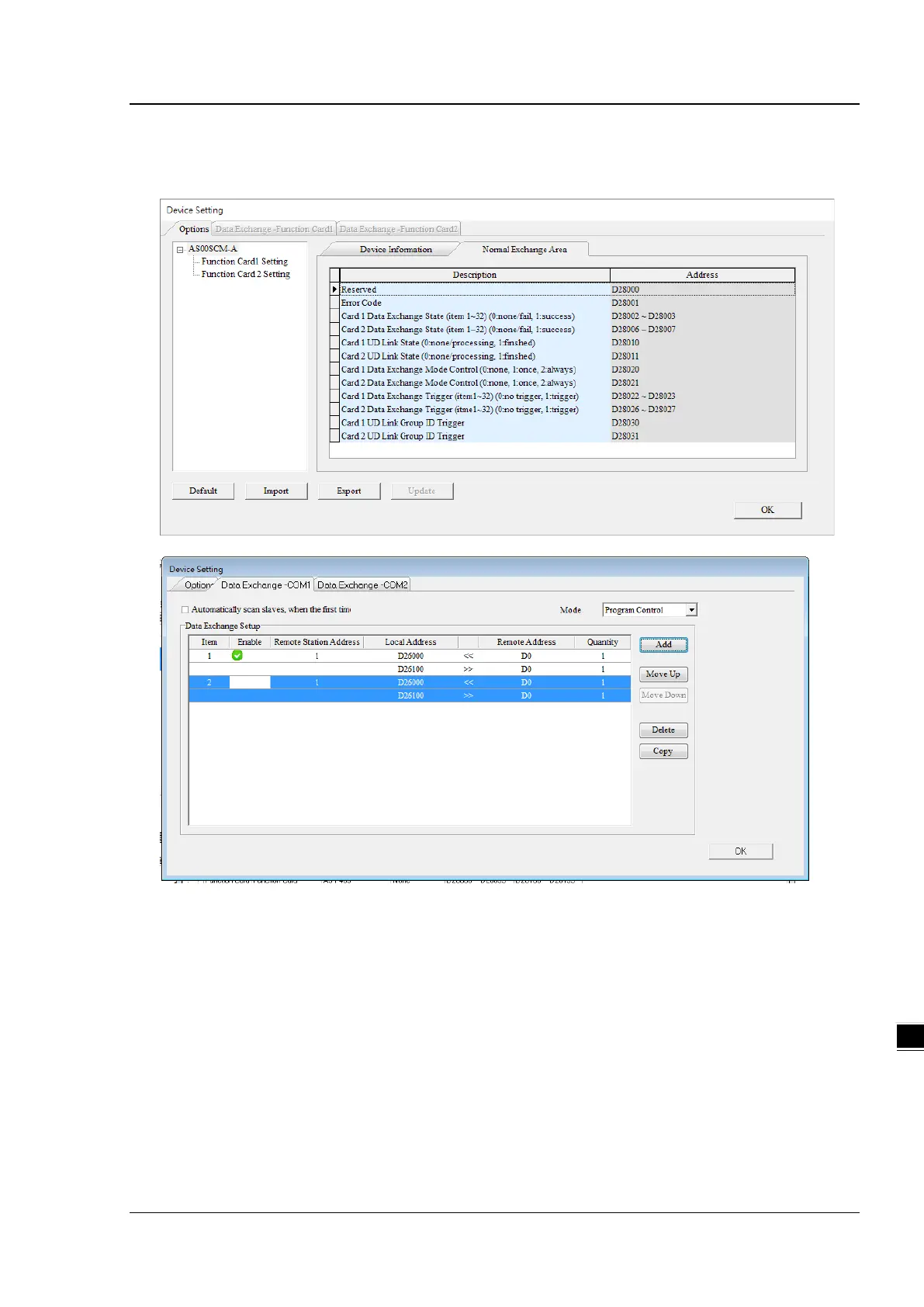
9.5 Normal Exchange Area
1) COM mode
In the examples above, note that the Normal Exchange Area shows the corresponding data registers of the
module and the PLC.
Module Status: 0 = stop, 1 = run
Error Code: refer to Section 9.7 for more information.
Card 1 & Card 2 Data Exchange State: occupies 4 data registers (32-bit data); each bit 1–32 represents the
state of the corresponding data point 1–32 to be exchanged: 0 = none/fail, 1 = success.
Card 1 & Card 2 Data Exchange Mode Control: set the data register to 0: none, 1: once, 2: always.
Card 1 & Card 2 Data Exchange Trigger: occupies 4 data registers; each bit 1–32 represents the state of the
corresponding data point 1–32 to be exchanged: 0 = no trigger, 1 = trigger.
Card 1 & Card 2 UD Link Group ID Trigger: set the group ID to be triggered.
 Loading...