17
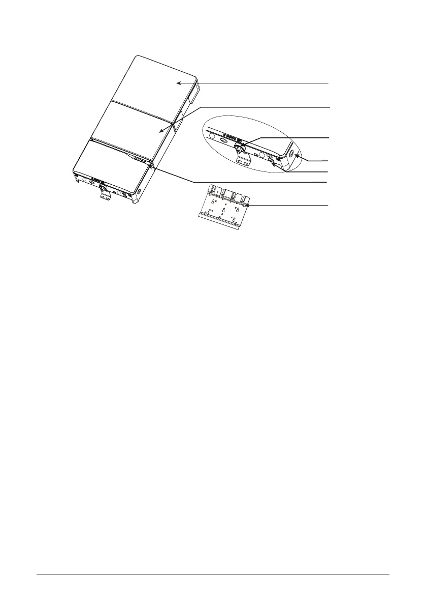
2.7 Equipment overview
(1) Inverter Power Box
(2) DC-DC box
(3) Lockable DC Disconnect
(4) Wiring Box
(5) Conduit Plugs
(6) LED Indicator
(7) Wall Mounting Plate
Figure 10: Exterior view of inverter main components
A further description of the equipment features:
(1) Inverter Power Box - This is the inverter section of the assembly. This section is sealed at the
factory and there are no user-serviceable parts inside. All wiring to install the inverter is done in
the wiring box.
(2) DC-DC box - It is used to connect inverter bus and EV battery to realize voltage conversion and
isolation functions.
(3) Lockable DC Disconnect - The DC disconnect is lockable per the UL code and allows the PV
power to be switched o to the inverter.
(4) Wiring Box - This is the compartment where all the wiring for the inverter inputs and outputs
plus the RS485 communication are done.
(5) Conduit Plugs - There are 5 - 3/4“ conduit openings and 2 - 1/2“ conduit openings. Each conduit
opening comes tted with a conduit plug that should be removed before installing conduit ttings.
Conduit ttings need to be water tight with either NEMA 4, 4X, 6, or 6X rated, and insulated type is
preferred.
(6) LED indicator - The ve LED lights indicate errors or status as described in section 5.1.
(7) Wall Mounting Plate - The inverter ships with a mounting plate that allows easy attachment of
the inverter to a wall.
(1)
(4)
(3)
(5)
(7)
(2)
(6)
 Loading...