3
Input
The standard DTE main unit is attached with 3 channels of inputs. You can purchase additional DTE20P to expand the number of input
channels. DTE supports maximum 6 channels of inputs which belong to group INA and group INB. Each group possesses 3 input channels.
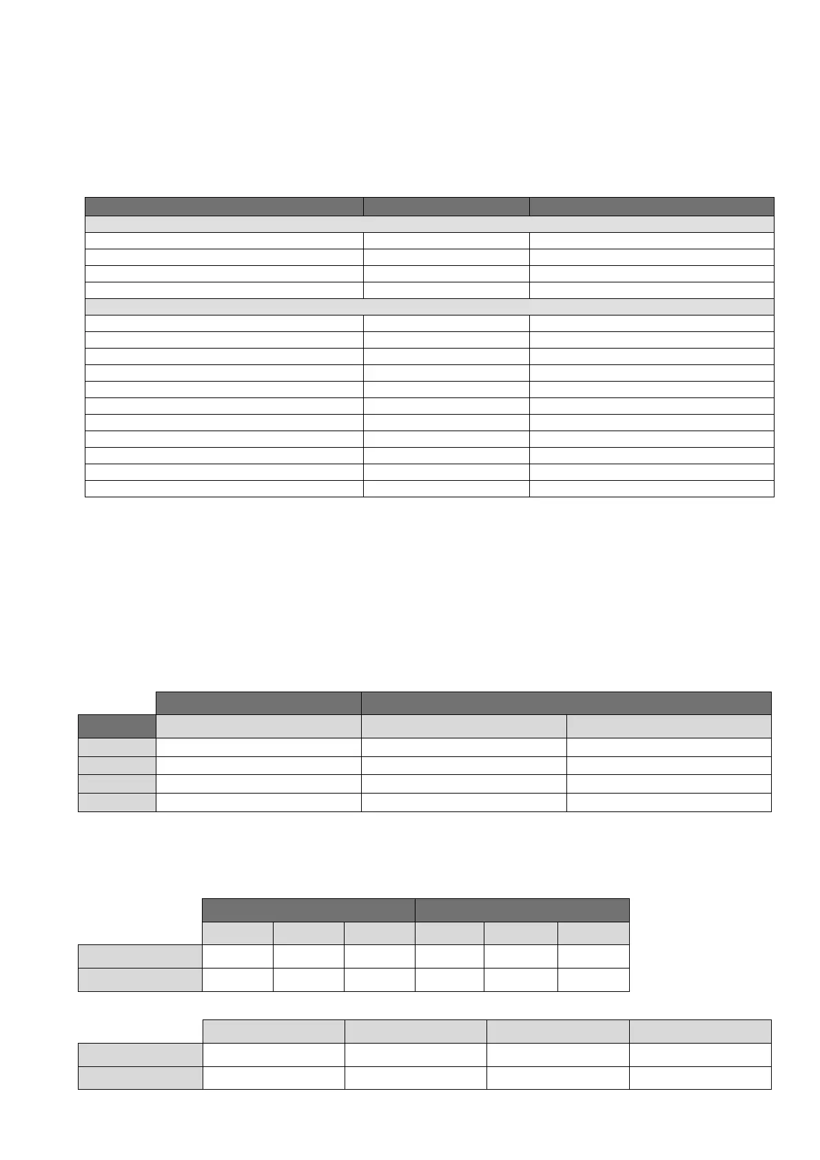
DTE series supports the following input sensors:
Input Sensor Type Register Value Range
For DTE10P / DTE20P
Temperature measurement resistance (Cu50) 14 -50 ~ 150°C
Temperature measurement resistance (Ni120) 13 -80 ~ 300°C
Platinum resistance (Pt100) 12 -200 ~ 600°C
Platinum resistance (JPt100) 11 -20 ~ 400°C
For DTE10T / DTE20T
Thermocouple TXK type 10 -200 ~ 800°C
Thermocouple U type 9 -200 ~ 500°C
Thermocouple L type 8 -200 ~ 850°C
Thermocouple B type 7 100 ~ 1,800°C
Thermocouple S type 6 0 ~ 1,700°C
Thermocouple R type 5 0 ~ 1,700°C
Thermocouple N type 4 -200 ~ 1,300°C
Thermocouple E type 3 0 ~ 600°C
Thermocouple T type 2 -200 ~ 400°C
Thermocouple J type 1 -100 ~ 1,200°C
Thermocouple K type 0 -200 ~ 1,300°C
Note: The default setting in DTE10T is “thermocouple K type”. The default setting in DTE10P is “Pt100".
Communication address: Input sensor types at H10A0 ~ H10A7; input upper limits at H1010 ~ H1017; input lower limits at H1018 ~ H101F.
Output
DTE supports maximum 12 channels of outputs, belonging to output groups OUT1, OUT2, SUB1 and SUB2, each group with 4 channels. See
the explanations below for how input channels correspond to output groups.
Without group INB (3 channels of input): Every channel corresponds to 2 groups of output and 2 groups of alarms. OUT1 and SUB1 are for
control output, and OUT1 can be used for proportional output. OUT2 and SUB2 are fixed for alarm output.
With group INB (6 channels of input): Every channel is paired with 2 groups of outputs. OUT1 and OUT2 are used for control output or
proportional output of CH1 ~ CH6. SUB1 and SUB2 are used for control output or alarm output.
See Table 1 for the relations between input and output.
3 channels of input 6 channels of input
Output Group INA (CH1 ~ CH3) INA (CH1 ~ CH3) INB (CH4 ~ CH6)
OUT1 Main control output or proportional output Main control output or proportional output No corresponding output
OUT2 Alarm 1 output No corresponding output Main control output or proportional output
SUB1 Control output Control output or alarm output No corresponding output
SUB2 Alarm 2 output No corresponding output Control output or alarm output
Table 1
Note: SUB1 and SUB2 do not support DTE20L and DTE20C. Please install the optional output modules you purchase into the correct slot.
Communication Address of Output & How to Set up Parameters:
See Table 2 for the communication addresses of output and Table 3 for the definition of the value in the address.
INA INB
CH1 CH2 CH3 CH4 CH5 CH6
OUT1, OUT2 H10A8 H10A9 H10AA H10AB H10AC H10AD
SUB1, SUB2 H10B0 H10B1 H10B2 H10B3 H10B4 H10B5
Table 2
Value = 0 Value = 1 Value = 2 Value = 3
OUT1, OUT2** Heating control Cooling control Proportional output Disable output
SUB1, SUB2** Heating control Cooling control Alarm output* Disable output
 Loading...