5
4. Any of the input temperatures has not been stabilized.
5. Input signal error.
6. The Input low voltage (less than 4V)
Synchronous Communication Protocol & Auto ID Setup
This function allows the auto setup of communication protocol in extension module DTC2000 and DTC2001 following the communication
protocol set in the DTE main unit. The station IDs of DTC decrease. See below for the steps.
1. Set the auto communication ID of DTE as “1” (communication address: H10F8).
2. Switch off DTE. Connect DTE with extension module DTC2000, DTC2001 and switch on DTE again.
3. Default communication protocol: 9,600bps, 7 bits, Even, 1 stop bit, communication address = 01.
4. This function will consume 3 ~ 5 seconds more when you switch on DTE.
PV value adjustment
Function:
PV = measure value * ( 1 + gain / 1000 ) + offset
How to operate:
Set up relevant parameters using the table below.
INA+INB CH1 CH2 CH3 CH4 CH5 CH6
Gain 1020H 1021H 1022H 1023H 1024H 1025H
Offset 19B8H 19B9H 19BAH 19BBH 19BCH 19BDH
Channel Disable
Function:
Disable the channel without use.(10F6H)
How to operate:
For example, if disable the CH3 & CH5, write the data : 0 0 0 1 0 1 0 0 (14H)
Bits in 10F6H Bit5 Bit4 Bit3 Bit2 Bit1 Bit0
Disable channel CH6 CH5 CH4 CH3 CH2 CH1
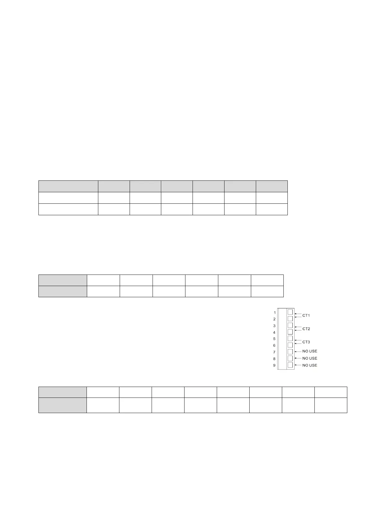
CT and adjustment (Current Transformer)
Function:
DTE10P offers maximum 3 channels of CT (CT1 ~ CT3), responsible for monitoring the current in INA.
Each CT group can be set up independently. With alarm outputs, when the detected current value is
beyond the allowed range, the corresponding alarm will be enabled.
Slot INA offers 3 channels of input, and CH1 ~ CH3 correspond to the current detected at CT1 ~ CT3.
Hardware requirement: Accessory DTE2CT inserted in the slot AUX.
How to operate:
1. Enable the CT function: Write 1234H into the address 47F1H and then 0004H into address 4824H.
Bits in 4824H Bit7 Bit6 Bit5 Bit4 Bit3 Bit2 Bit1 Bit0
Flag --
Hot runner
control
Slop
control
-- Latch CT EVENT --
Notes:
The flag to enable CT is at bit2 of 4824H. Write 0004H to bit2 to set it on.
If the “multistate” function is enabled, for example, writing in 0024H means enabling bit5 and bit2 at the same time.
You can only choose to use either the CT or EVENT function.
If there is already a set value in 4824H and you would like to modify it, reset it to 0 before you set up a new value.
CT auto adjustment: Insert CT card without terminal first, write 1234H into the address 47F1H and then write 1234H into address
482CH.
Reading address 482C, if response 0000H means adjustment finish, if response 0001H means in adjustment status not finish.
2. When you use INA input or INA + INB input, set up relevant parameters using the table below.
 Loading...