- 1 -
………………………………………………………………… ENGLISH …………………………………………………………………
Thank you for choosing Delta’s DVP-ES2 series PLC. DVP-ES2 series provides 16~ 80
points PLC and 8 ~ 32 points digital I/O module. The maximum I/O points including
those on the PLC are 256 points. DVP-ES2 series PLCs satisfy various applications in
that they can be used with analog input/output modules. Users do not have to install any
batteries in DVP-ES2 series PLCs. The PLC programs and the latched data are stored
in the flash memories.
EN DVP-ES2 is an OPEN-TYPE device. It should be installed in a control cabinet
free of airborne dust, humidity, electric shock and vibration. To prevent
non-maintenance staff from operating DVP-ES2, or to prevent an accident from
damaging DVP-ES2, the control cabinet in which DVP-ES2 is installed should be
equipped with a safeguard. For example, the control cabinet in which DVP-ES2 is
installed can be unlocked with a special tool or key.
EN DO NOT connect AC power to any of I/O terminals, otherwise serious damage
may occur. Please check all wiring again before DVP-ES2 is powered up. After
DVP-ES2 is disconnected, Do NOT touch any terminals in a minute. Make sure
that the ground terminal on DVP-ES2 is correctly grounded in order to
prevent electromagnetic interference.
FR DVP-ES2 est un module OUVERT. Il doit être installé que dans une enceinte
protectrice (boitier, armoire, etc.) saine, dépourvue de poussière, d’humidité, de
vibrations et hors d’atteinte des chocs électriques. La protection doit éviter que
les personnes non habilitées à la maintenance puissent accéder à l’appareil (par
exemple, une clé ou un outil doivent être nécessaire pour ouvrir a protection).
FR Ne pas appliquer la tension secteur sur les bornes d’entrées/Sorties, ou l’appareil
DVP-ES2 pourra être endommagé. Merci de vérifier encore une fois le câblage
avant la mise sous tension du DVP-ES2. Lors de la déconnection de l’appareil,
ne pas toucher les connecteurs dans la minute suivante. Vérifier que la terre est
bien reliée au connecteur de terre afin d’éviter toute interférence
électromagnétique.
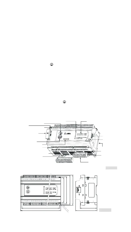
Product Profile & Dimension
R
DVP40ES2
24DI / 1 6DO
POWER, RUN, ERROR & COM indicators
Input/Output terminal numbers
DIN rail clip
Direct mounting hole
COM1 communication port
(RS-232C)
Input /Output indicators
Remo v a bl e terminal b lock
DIN rail groove (35mm)
I/O module connector
Run/Stop switch
COM2/ COM3 (RS-485)
Input/Output terminal numbers
I/O module clip
Output type
Model name
Memory card slot*
[ Fi g ure 1 ]
Ethernet port(E S2-E)
*: Only DVP40ES200RM and ES2-E models support a memory card slot.
[ Fi gure 2 ]
106
98
L1
L 78
90
61.5
110
Unit: mm

 Loading...


