- 1 -
………………………………………………………………… ENGLISH …………………………………………………………………
Thank you for choosing Delta’s DVP series PLC. Delta releases DVP01LC-SL, which
can be used to measure weights. DVP01LC-SL is applicable to 4-wire or 6-wire load
cells with various eigenvalues. Therefore, the response time can be adjusted in
accordance with users’ needs. On this basis, the requirements of load application
markets can easily be met.
EN DVP01LC-SL is an OPEN-TYPE device. It should be installed in a control cabinet
free of airborne dust, humidity, electric shock and vibration. To prevent
non-maintenance staff from operating DVP01LC-SL, or to prevent an accident
from damaging DVP01LC-SL, the control cabinet in which DVP01LC-SL is
installed should be equipped with a safeguard. For example, the control cabinet
in which DVP01LC-SL is installed can be unlocked with a special tool or key.
EN DO NOT connect AC power to any of I/O terminals, otherwise serious damage
may occur. Please check all wiring again before DVP01LC-SL is powered up.
After DVP01LC-SL is disconnected, Do NOT touch any terminals in a minute.
Make sure that the ground terminal on DVP01LC-SL is correctly grounded in
order to prevent electromagnetic interference.
FR DVP01LC-SL est un module OUVERT. Il doit être installé que dans une enceinte
protectrice (boitier, armoire, etc.) saine, dépourvue de poussière, d’humidité, de
vibrations et hors d’atteinte des chocs électriques. La protection doit éviter que
les personnes non habilitées à la maintenance puissent accéder à l’appareil (par
exemple, une clé ou un outil doivent être nécessaire pour ouvrir a protection).
FR Ne pas appliquer la tension secteur sur les bornes d’entrées/Sorties, ou l’appareil
DVP01LC-SL pourra être endommagé. Merci de vérifier encore une fois le
câblage avant la mise sous tension du DVP01LC-SL. Lors de la déconnection de
l’appareil, ne pas toucher les connecteurs dans la minute suivante. Vérifier que la
terre est bien reliée au connecteur de terre afin d’éviter toute interférence
électromagnétique.
Product Profile & Dimensions
3 mm
90 mm
33 mm
60 mm
CH1
MAX
MOTION
ERROR
ZER O
NET
L.V
POWER
RUN
SEN+
SEN-
SHD
SIG-
SIG+
EXC+
EXC-
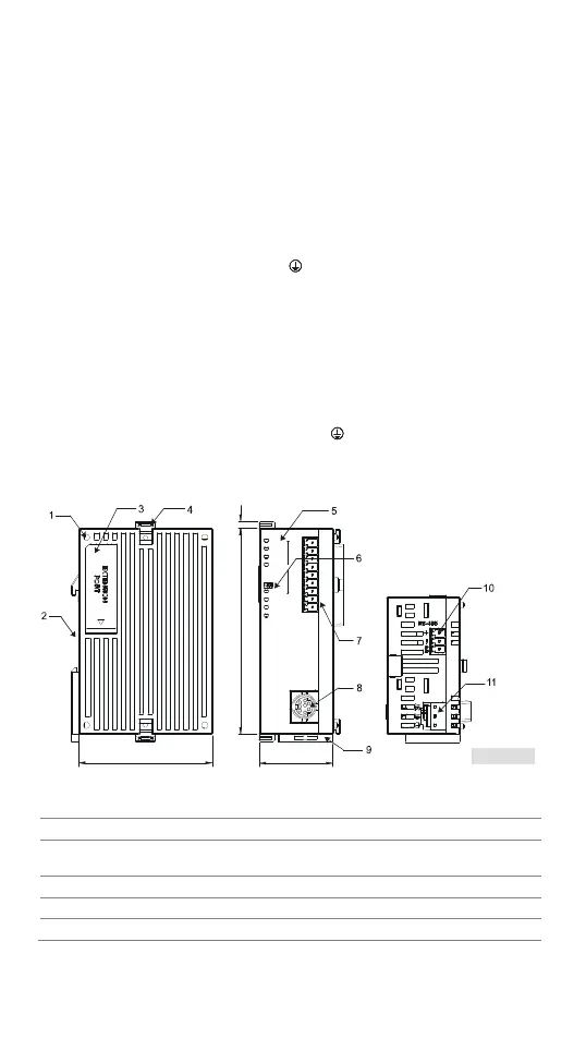
[ Figure 1 ]
1. Mounting hole of the I/O module 2. DIN rail mounting slot (35mm)
3. I/O module connection port 4. I/O module clip
5.
Status indicator
(POWER, RUN, ERROR and L.V)
6.
Function status indicator
(NET, ZERO, MAX, MOTION)
7. I/O terminals 8. RS-232 port
9. Mounting slot clip 10. RS-485 port
11. DC power input

 Loading...