- 2 -
I/O Terminal Layout
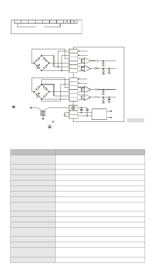
DVP0 1 L C-SL
SEN-SEN+SIG-SIG+EXC-EXC+ SHD
CH1
External Wiring
(100 or less)
SIG+
SIG-
SEN+
SEN-
*1
Term inal
of power
mo dul e
System
grounding
Grounding
[ Figure 2 ]
EXC+
EXC-
SIG+
SIG-
SEN+
SEN-
EXC+
EXC-
A+5V
AGND
A+5V
AGND
0V
24V
DC/DC
A+5V
AGND
Converter
4 strain guage
6 strain guage
Note 1: Please connect the terminal on both the power module and Load Cell module to the system
earth point and ground the system contact or connect it to the cover of power distribution
cabinet.
Electrical Specifications
Load cell module Voltage output
Rated power supply voltage/
power consumption
24 VDC (-15 to +20%) / 3W
Voltage Boundary 18 to 31.2 VDC
Max. current consumption 125 mA
Input signal range ± 40 mVDC
Sensibility +5 VDC +/-10%
Communication port RS-232, RS-485
Applicable sensor type 4-wire or 6-wire strain gauge
Temperature coefficient span ≤ ± 50 ppm/K v. E
Temperature coefficient zero
point
≤ ± 0.4 μV/K
Linearity error ≤ 0.02%
Response time 2, 10, 20, 40, 80, 200, 380 ms × channels
4 measuring ranges 0 to 1 mV/V, 0 to 2 mV/V, 0 to 4 mV/V, 0 to 6mV/V
Max. distance for connecting
to load cell
100 M
Max. current output 5 VDC * 300 mA
Permitted load cell resistance 40 to 4,010 Ω
Common mode rejection
(CMRR @50/60 Hz)
≥100dB
Dynamic value filter Setting range: K1 to K9

 Loading...