08SP11R
08SP11T
16SP11R 08SP11TS 16SP11TS
S /S
X0
X1
X2
X3
C0
Y0
C1
Y1
C2
Y2
C3
Y3
.
.
.
.
.
S /S
X0
X1
X2
X3
C0
Y0
Y1
Y2
Y3
Y4
Y5
Y6
Y7
X4
X5
X6
X7
S /S
X0
X1
X2
X3
UP
Y0
Y1
Y2
Y3
ZP
.
.
.
.
.
.
.
.
S /S
X0
X1
X2
X3
UP
Y0
Y1
Y2
Y3
Y4
Y5
Y6
Y7
X4
X5
X6
X7
ZP
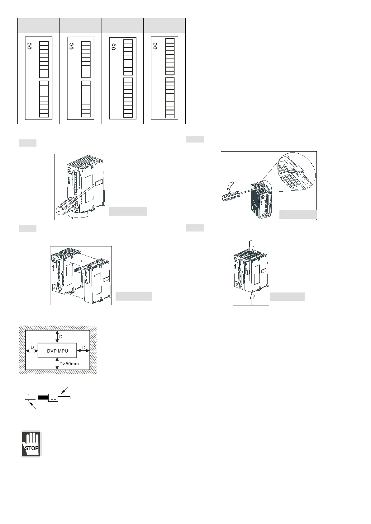
Connection
Step 1 Screw open the side cover of the extension unit,
and you will see the connection port.
Step 2 Lift the fixing clip by the screwdriver.
Step 3 Adjust the positioning hole of the MPU and the
extension unit. Meet the connection port on the MPU with
the extension unit to tightly connect the two.
Step 4 Fasten the fixing clip on the extension unit to
complete the connection.
Installation & Wiring
Install the PLC in an enclosure with sufficient space around it to allow heat dissipation (as shown in the figure below).
DVP-
PLC can be secured to a cabinet by using the DIN rail of 35mm in height and 7.5mm in
depth. When mounting PLC to the DIN rail, be sure to use the end bracket to stop any
side-to-side movement of the PLC and reduce the chance of wires being loosen. A small
retaining clip is at the bottom of the PLC. To secure PLC to the DIN rail, place the clip onto
the rail and gently push it up. To remove it, pull the retaining clip down and gently
PLC from the DIN rail.
1. Use 22-16AWG (1.5mm) single or multiple core wire on I/O wiring terminals. The
specification of the terminal is shown in the figure on the left hand side. The PLC terminal
screws shall be tightened to 1.95kg-cm (1.7 in-lbs). Use 65/75°C copper wires only.
2. DO NOT place the I/O signal wires and power supply wire in the same wiring duct.
Notes
DO NOT install PLC in an environment with
Dust, smoke, metallic debris, corrosive or flammable gas
High temperature, humidity
Direct shock and vibration
During the engineering
1. DO NOT drop tiny metallic conductor into the PLC when screwing and wiring.
2. There should be a margin of more than 50mm between the PLC and other control devices, and the PLC should be
placed away from high voltage wire and power equipment.
 Loading...


