Arrangement of I/O Points
No matter the MPU with how many points you are using, the input point No. of the first connected extension unit has to
start from X20 and output point No. from Y20. The MPU is able to connect to maximum 14 digital extension units. The
connection of MPU and extension units is demonstrated in the figure below.
PLC Model
Input
points
Output
points
Input point No. Output point No.
MPU SS/SA/SX/SC 8 4/6 X0 ~ X7, X10, X11 Y0 ~ Y5, X10, X11
EXT1 16SP11T 8 8 X20 ~ X27 Y20 ~ Y27
EXT2 08SM11N 8 0 X30 ~ X37 -
EXT3 06SN11R 0 6 - Y30 ~ Y35
EXT4 08SP11R 4 4 X40 ~ X43 Y40 ~ Y43
The 3
rd
extension module 06SN11R will be regarded as 8-point output. The 2 output points of bigger No. will have no
actual corresponding output points.
The 4
th
extension module 08SP11R will be regarded as 8-point input/8-point output. The 4 input points and 4 output
points of bigger No. will have no actual corresponding input/output points. Therefore, it is suggested that they placed in
the end of the series connection to make the No. of I/I points continuous.
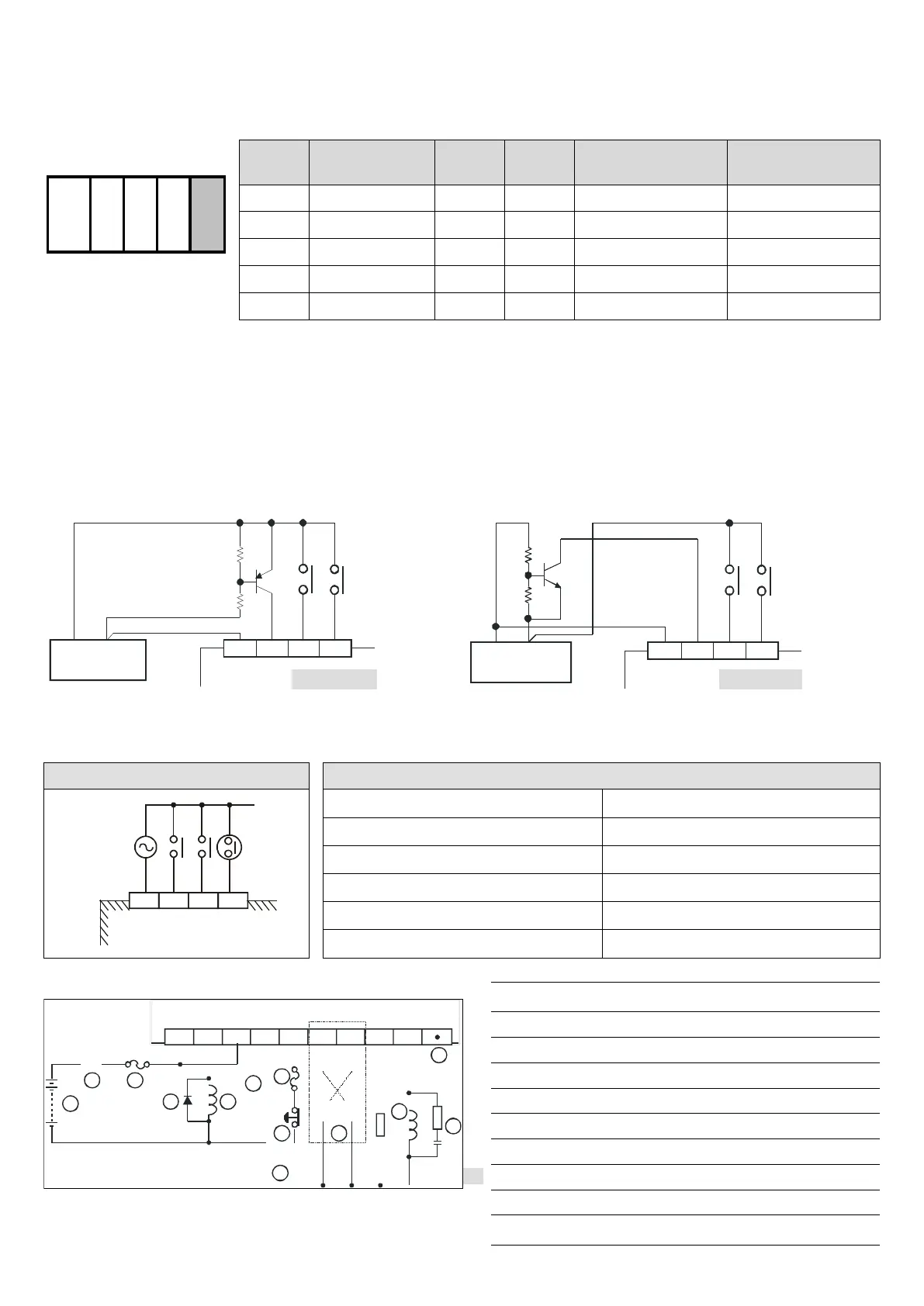
Input Point Wiring & Specification
There are two types of signals at input points, DC and AC, and there are two types of DC inputs, Sink and Source. The
wiring is as follows.
+24V 0V
DC Power Supply
+24V 0V
DC Power Supply
S/S X0 X1 X2
Source mode
S/S X0 X1 X2
Source mode
[ F i gure 7 ]
+24V 0V
DC Power Supply
+24V 0V
DC Power Supply
S/S X0 X1 X2
Sink mode
S/S X0
X1 X2
Sink mode
[ Figure 8 ]
AC Wiring:
Wiring Loop 110VAC Input Specification
85~132VAC
50/60Hz
COM X0 X1 X2
DVP08SM10N
Prox.
Sensor
Input voltage 85 ~ 132VAC, 50 ~ 60Hz
Input resistance 19Kohm/50Hz, 16Kohm/60Hz
Input current 9.2mA 110VAC/60Hz
On/Off voltage level 79V 3.8mA/30V 2.5mA
Response time 15ms
Circuit isolation/operation instruction By photocoupler / LED On
Relay Output Wiring Circuit (Sink):
MC
2MC1
9
10
C0 C1Y0
Y4
C2
Y2
Y3
Y5
Y1
5 2
3
7
8
1
6
7
2
5 4
MC2
MC1
DO NOT wire empty terminal
Fuse
Reverse current protection diode*1
Manual exclusive output*2
Emergency stop: by external switch
Surge absorber*3
Inductive load
Incandescent light (resistive load)
DC power supply
AC power supply
 Loading...


