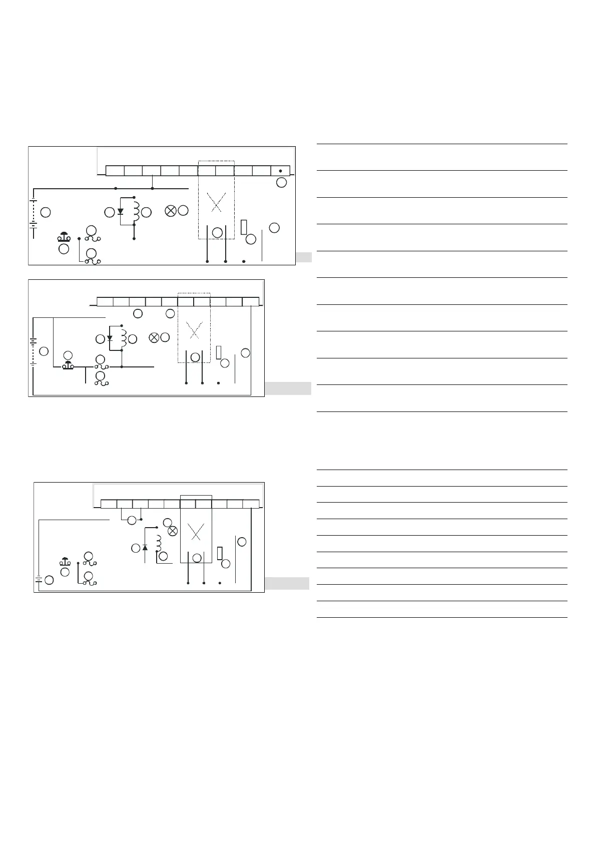
*1: There is no internal protection circuit in the output relay of the PLC; therefore when activating an inductive load,
we suggest you parallely connect a reverse current protection diode to extend the life of the contact.
- The diode has to be able to endure max. 5 ~ 10 times of load voltage.
- The positive current of the diode has to be bigger than load current.
*2: Manual exclusive output uses external circuit and forms an interlock, together with the PLC internal program, to ensure
safety protection in case of any unexpected errors.
*3: There is no internal protection circuit in the output relay of the PLC; therefore when activating an inductive load, we
suggest you parallely connect a surge absorber (0.1uF + “100ohm to 120ohm”) to reduce the noise on AC load and
extend the life of the contact.
Transistor Output Wiring Circuit (Sink):
MC2
MC1
C0 C1Y0
Y4
C2
Y2
Y3
Y5
Y1
5 7 8
1
6
6
4
MC2
MC1
2
3
3
9
M
C2
MC1
UP
Y0
Y4Y
2
Y3
Y
5
Y1
5
7 8
6
6
4
M
C2
MC1
2
3
9
Z
PY
6
Y7
3
10 10
DO NOT wire empty terminal
Emergency stop
Fuse
Manual exclusive output*1
DC power supply
Incandescent light (resistive load)
Reverse current protection diode*2
Inductive load
Resistive load
Y1, Y3 (refer to other wiring methods)
*1: Manual exclusive output uses external circuit and forms an interlock, together with the PLC internal program, to
ensure safety protection in case of any unexpected errors.
*2: Use a zener diode (39V) in the PLC to protect the transistor output. When activating inductive load, we sugget you
parallely connect a reverse current protection diode.
Transistor Output Wiring Loop (Source):
MC2
MC1
ZP Y6Y7
Y1
Y4
Y3
Y2
Y0
Y5
5
7
8
6
6
4
MC2
MC1
2
3
3
9
UP
1
Y6, Y7 (refer to other wiring methods)
Emergency stop
Fuse
Manual exclusive output*1
DC power supply
Incandescent light (resistive load)
Reverse current protection diode*2
Inductive load
Resistive load
*1: Manual exclusive output uses external circuit and forms an interlock, together with the PLC internal program, to
ensure safety protection in case of any unexpected errors.
*2: Use a zener diode (39V) in the PLC to protect the transistor output. When activating inductive load, we sugget you
parallely connect a reverse current protection diode.
 Loading...


