- 7 -
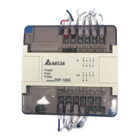
Transistor output (NPN) Transistor output (PNP)
VDC
+
Small er power
D
[ F ig ure 14a ]
D: 1N4001 diode or equi va lent com ponent
ZP
Y
UP
VDC
+
Smaller power
D
[ F ig ure 15a ]
D: 1N4001 diode or equi valent com ponent
Y
UP
ZP
ZD
D
VDC
+
Larger power and
frequent on/off
ZD: 9V Z ener, 5W
[ F ig ure 14b ]
D: 1N4001 diode or equi valent com ponent
ZP
Y
UP
ZD
D
Larger power
and
frequent on/off
ZD: 9V Z ener, 5W
[ F ig ure 15b ]
D: 1N4001 diode or equivalent com ponent
ZP
UP
VDC
+
Y
VDC
+
The output of the transistor model is “open collector”. If Y0/Y1 is set to pulse output, the
output current has to be bigger than 0.1A to ensure normal operation of the model.
1. Diode suppression: Used when in smaller power [Figure 14a] and [Figure 15a]
Diode + Zener suppression: Used when in larger power and frequent On/Off [Figure 14b]
Manually exclusive output: For example, Y2 and Y3 control the forward running and reverse
running of the motor, forming an interlock for the external circuit, together with the PLC
internal program, to ensure safe protection in case of any unexpected errors.
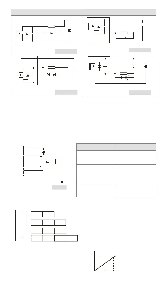
PWM DA output circuit wiring (Only for DVP-12SS211S)
Please refer to figure 1 below for more information about wiring.
DA
UP
+
2 4 V D C
ZP
+
V0
VR
Ri n
PWM
Y0
-
VR is con nected to Ri n in p aral lel.
The imp edan ce i s ab out 1.4 6 .
Load
[Figure 1]
Item Specifications
DA range
0~10VDC
Value range
0~100
Resolution*1
0.1V (1~9V)
Output impedance
2kΩ
Minimum load
1.5kΩ
D/A conversion time
<70ms
*1: 1~9V is a linear area. The resolution is 0.1V. 0~1V and 9~10V are nonlinear areas. The
output probably can not reach the voltage set.
Please refer to the correction formula before you use the PWM DA output function.
M1002
SET
M1116
M0
PWM
D0
Y0
MOV
K100
D2
MOV
K50
D0
D2
Please refer to the explanation of PWM for
more information about setting the time unit
for the pulses output by Y0.
Set the pulse cycle to 100µs.
Set the duty cycle of a pulse to 50%.
Set M0 to ON. Adjust the variable resistor so
that V0 is 5V, as shown in the curve below.
 Loading...