Quick Installation Guide
Grid-tie Transformerless Solar Inverter
H2.5 / H3 / H3A / H4A / H5A_220 / H5A_221
Caution
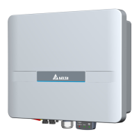
Descriptions of Parts and Components
Dimensions and Function Introduction
②
Object
PV Inverter
Quick Installation Guide
AC Plug
Wall-Mount
Bracket
Qty
1
1
1
1
Description
Solar inverter
Important safety instructions and technical specifications
should be followed during installation.
Connector for AC connection
DC Plug
①
②
③
⑤
④
2 pairs
1 pair
MC4 connector for DC connection for H3A / H4A / H5A
MC4 connector for DC connection for H2.5 / H3
To mount the solar inverter securely on the wall.
If there is any visible damage to the inverter/accesories or any damage to the
packaging, please contact your inverter supplier before installation.
380
130
91
318
346.8
Grounding
AC connector
Label
DC connectors Comm. Interface
DC
switch
LED and Button
The LEDs indicate the operating state of the inverter.
The reset button function
Status Explanation
Steady on
The red LED glowing indicates error or fault.
( see user manual - chapter 9.1 Error Message )
Steady on The inverter is connected to the grid.
Flashing The red LED flashing indicates error "E34:Insulation"
Flashing The inverter is on countdown status, before connecting grid.
Steady on The Wi-Fi module is on data transmission.
LED
Earth Fault
Alarm
Grid
Wi-Fi
Wi-Fi LED Status Explanation
Wi-Fi LED flashing once every
one seconds
Reset Wi-Fi module, and Wi-Fi password
returns to the default: DELTASOL
Wi-Fi LED flashing once every
half a second
Reset Wi-Fi module
Operation
Push 3s~10s
Push 20s~
No flash No functionPush 10s~20s
Mounting
227
60
7.5
22.5
37.5
46
250
291
Φ6.0*6
①
②
③
More operation procedure please scan QR-code to user manual.
More DC1_100 details please scan QR-code to user manual.
Setting of APP please scan QR-code to APP guideline.
https://mydeltasolar.deltaww.com/index.php?p=manual
http://www.deltaww.com/Products/CategoryListT1.aspx?CID=05
010101&PID=4481&hl=en-US&Name=H2.5-5A
https://mydeltasolar.deltaww.com/?p=product_manual
During operation of electrical devices, certain parts are under dangerous voltage.
Inappropriate handling can lead to physical injury and material damage.
Always adhere to the installation regulations.
Installation may only be conducted by certified electricians.
Warning
Do not install the unit near or on flammable surfaces.
Mount the unit tightly on a solid/smooth surface.
When the photovoltaic array is exposed to light, it supplies a DC voltage to the Inverter,
a shock hazard may exist due to output wires or exposed terminals.
To reduce the risk of shock during installation, cover the array with an opaque (dark)
material
and ensure that the Disconnect Device in the inverter is set to OFF before
commencing any wiring.
Before commencing AC wiring, please ensure all AC circuit breakers are switched off.
Caution
The maximum open circuit voltage of the PV Array must not exceed 500Vdc (H2.5) /
600Vdc (H3/ H3A/ H4A/ H5A) .
unit: mm
unit: mm
①
③ ⑤
④
For H3A / H4A / H5A
For H3 / H2.5
5013280700