15
Fig. 22
Fig. 21
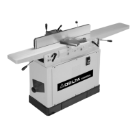
MOTOR PULLEY AND BELT GUARD
Assemble the motor pulley and belt guard (A) Fig. 19, to
the jointer base using the four M6x1x10mm cheese head
screws, two of which are shown at (B), and four M6.1
lockwashers.
MAKE CERTAIN MOTOR PULLEY IS
NOT CONTACTING GUARD.
If motor pulley is contacting the guard, adjust the motor
pulley, see the section “BELT, ALIGNING PULLEYS,
AND ADJUSTING BELT TENSION.”
Fig. 20
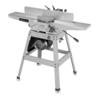
FENCE
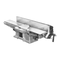
1. Insert hexagon rod (A) Fig. 20, of fence assembly into
bracket (B) on jointer as shown.
Fig. 19
2. Remove the M8x1.25x12mm long screw (D) and
M8.4 flat washer (E) from the end of hexagon rod.
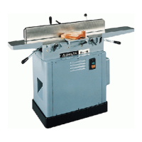
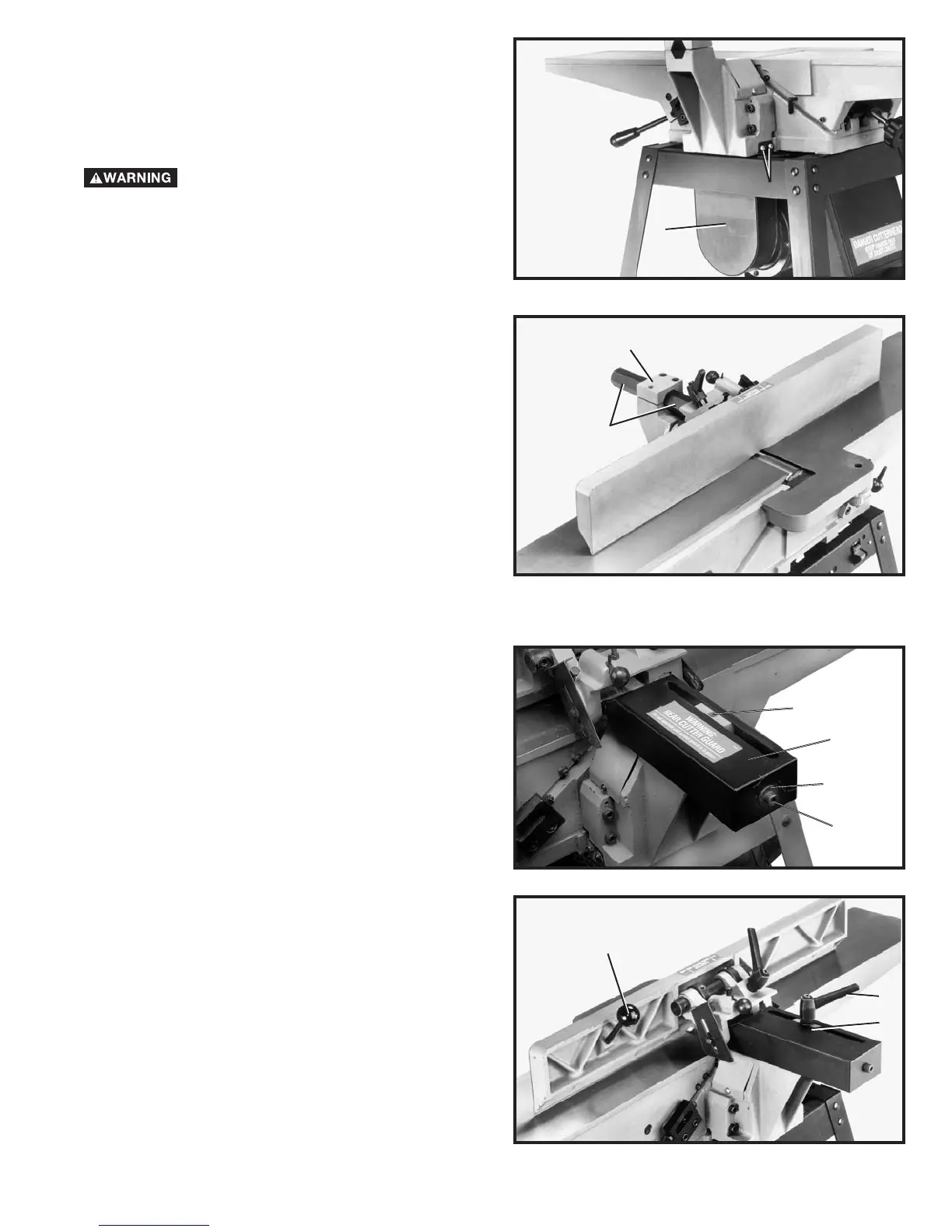
Assemble rear cutterhead guard (C) Fig. 21, to end of
hexagon rod using the M8x1.25x12mm long screw (D)
and M8.4 flat washer (E).
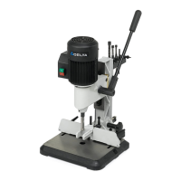
3. Thread fence locking handle assembly (F) Fig. 22,
and M8.4 flat washer (G) into hole (Z) Fig. 21. Lock
handle (F) Fig. 22, is spring-loaded and can be
repositioned by pulling out the handle and repositioning
it onto the serrated nut located under the handle.
4. Thread fence tilting handle (H) Fig. 22, to threaded
hole in back of fence as shown.
A
B
A
B
H
F
G
Z
C
E
D
 Loading...