Chapter 7 Optional AccessoriesMS300
92
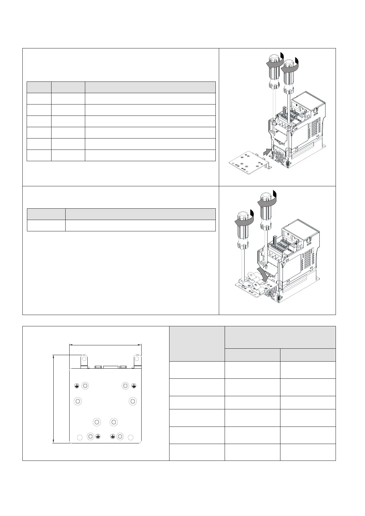
Installation
(This example uses Frame A model)
1. As shown in the right figure, fix the shield plate on the AC
motor drive.
Torque value:
6–8 kg-cm / (5.2–6.9 lb-in.) / (0.59–0.78 Nm)
6–8 kg-cm / (5.2–6.9 lb-in.) / (0.59–0.78 Nm)
6–8 kg-cm / (5.2–6.9 lb-in.) / (0.59–0.78 Nm)
4–6 kg-cm / (3.5–5.2 lb-in.) / (0.39–0.59 Nm)
4–6 kg-cm / (3.5–5.2 lb-in.) / (0.39–0.59 Nm)
6–8 kg-cm / (5.2–6.9 lb-in.) / (0.59–0.78 Nm)
2. Select a suitable R-clip according to the wire gauge used,
and then fix the R-clip on the shield plate.
6–8 kg-cm / (5.2–6.9 lb-in.) / (0.59–0.78 Nm)
Dimensions of EMC Shield Plate
Figure 7-39
Dimensions of Shield Plate
Unit: mm (inch)
 Loading...
