22
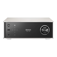
ADV-M51
NOTE FOR SCHEMATIC DIAGRAM
1. WARNING:
Parts marked with this symbol have critical character-
istics.
Use ONLY replacement parts recommended by the manu-
facturer.
2. CAUTION:
Before returning the unit to the customer, make sure you
make either (1) a leakage current check or (2) a line to
chassis resistance check. If the leakage current exceeds
0.5 milliamps, or if the resistance from chassis to either
side of the power cord is less than 460 kohms, the unit is
defective.
3. WARNING:
DO NOT return the unit to the customer until the problem
is located and corrected.
4. NOTICE
ALL RESISTANCE VALUES IN OHM. k=1,000 OHM
M=1,000,000 OHM
ALL CAPACITANCE VALUES IN MICRO FARAD.
p=MICRO-MICRO FARAD
EACH VOLTAGE AND CURRENT ARE MEASURED AT
NO SIGNAL INPUT CONDITION.
CIRCUIT AND PARTS ARE SUBJECT TO CHANGE
WITHOUT PRIOR NOTICE.
SIGNAL LINE
配線図について
注)
1. 指定なき抵抗値は Ω、k は kΩ、M は MΩ を示
す。
2. 指定なきコンデンサーの値は
µF、pはpFを示
す。
3. 各部の電圧は無信号の値を示す。
4. この配線図は基本配線図です。改良等のため変更
することがありますのでご了承ください。
印の部品は安全を維持するために重要な部品です。
従って交換時は必ず指定の部品を使用してください。
SIGNAL LINE
 Loading...