27
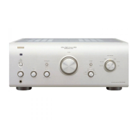
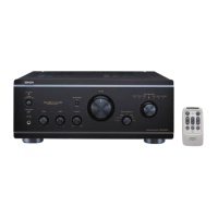
PMA-2000AE
NOTE FOR SCHEMATIC DIAGRAM
1. WARNING:
Parts marked with this symbol have critical charac-
teristics.
Use ONLY replacement parts recommended by the
manufacturer.
2. CAUTION:
Before returning the unit to the customer, make sure you
make either (1) a leakage current check or (2) a line to
chassis resistance check. If the leakage current exceeds
0.5 milliamps, or if the resistance from chassis to either
side of the power cord is less than 460 kohms, the unit is
defective.
3. WARNING:
DO NOT return the unit to the customer until the problem
is located and corrected.
4. NOTICE
ALL RESISTANCE VALUES IN OHM. k=1,000 OHM
M=1,000,000 OHM
ALL CAPACITANCE VALUES IN MICRO FARAD.
p=MICRO-MICRO FARAD
EACH VOLTAGE AND CURRENT ARE MEASURED AT
NO SIGNAL INPUT CONDITION.
CIRCUIT AND PARTS ARE SUBJECT TO CHANGE
WITHOUT PRIOR NOTICE.
5. NOTICE
GND of signal circuit is connected to GND of control cir-
cuit through chassis.
In observing signals detaching the INPUT P.W.B. or the
CONTROL P.W.B. from the chassis, please connect the
grounding point (Grounding side on INPUT P.W.B.,
W602 on CONTROL P.W.B.) to chassis.
配線図について
注)
1. 指定なき抵抗値は Ω、k は kΩ、M は MΩ を示す。
2. 指定なきコンデンサーの値は µF、p は pF を示す。
3. 各部の電圧は無信号の値を示す。
4. この配線図は基本配線図です。改良等のため変更するこ
とがありますのでご了承ください。
5. このセットは信号系のグランドと制御系のグランドが
別々にシャーシに接続されています。セットから基板を
外して通電する場合には、入力基板の信号グランドとコ
ントロール基板のシャーシグランド (W602) を必ずセッ
トのシャーシに接続してください。
印の部品は安全を維持するために重要な部品です。
従って交換時は必ず指定の部品を使用してください。
 Loading...