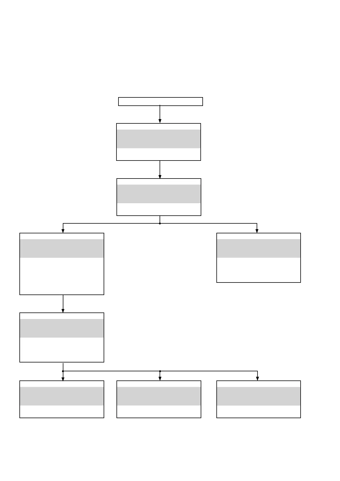
DISASSEMBLY
• Remove each part following the ow below.
• Reassemble the removed parts in the reverse order.
• Read "Precautions During Work" before reassembling the removed parts.
• If wire bundles are removed or moved during adjustment or part replacement, reshape the wires after completing
the work. Failure to shape the wires correctly may cause problems such as noise.
LOADER PANEL ASSY
See "DISASSEMBLY"
1. LOADER PANEL ASSY
and "EXPLODED VIEW"
LOADER PANEL
Ref. No. of EXPLODED VIEW : P 2
TOP COVER
FRONT PANEL ASSY
See "DISASSEMBLY"
2. FRONT PANEL SUB ASSY
and "EXPLODED VIEW"
FRONT PANEL PCB
Ref. No. of EXPLODED VIEW : C 1
SPEAKER PCB
See "DISASSEMBLY"
7. SPEAKER PCB
and "EXPLODED VIEW"
SPEAKER PCB
Ref. No. of EXPLODED VIEW : C 6a
MCU PCB
See "DISASSEMBLY"
6. MCU PCB
and "EXPLODED VIEW"
MCU PCB
Ref. No. of EXPLODED VIEW : C 11
HEAT SINK SUB ASSY
See "DISASSEMBLY"
4. HEAT SINK SUB ASSY
and "EXPLODED VIEW"
CONNECT PCB
Ref. No. of EXPLODED VIEW : C 2
AMP PCB
Ref. No. of EXPLODED VIEW : C 3
HEAT SINK
Ref. No. of EXPLODED VIEW : M 4
POWER and CONNECT PCB
See "DISASSEMBLY"
5. POWER and CONNECT PCB
and "EXPLODED VIEW"
POWER PCB
Ref. No. of EXPLODED VIEW : C 5a
CONNECT PCB
Ref. No. of EXPLODED VIEW : C 4
TRANS
See "DISASSEMBLY"
8. TRANS
and "EXPLODED VIEW"
TRANS
Ref. No. of EXPLODED VIEW : C 14
CD MECHA ASSY
See "DISASSEMBLY"
3. CD MECHA ASSY
and "EXPLODED VIEW"
DC-DC PCB
Ref. No. of EXPLODED VIEW : C 8
CD MECHA
Ref. No. of EXPLODED VIEW : C 16
12

 Loading...