25
ENGLISH
• Disconnect the plug from the supply.
• Cut off the plug and dispose of it safely; a plug
with bared copper conductors is dangerous if
engaged in a live socket outlet.
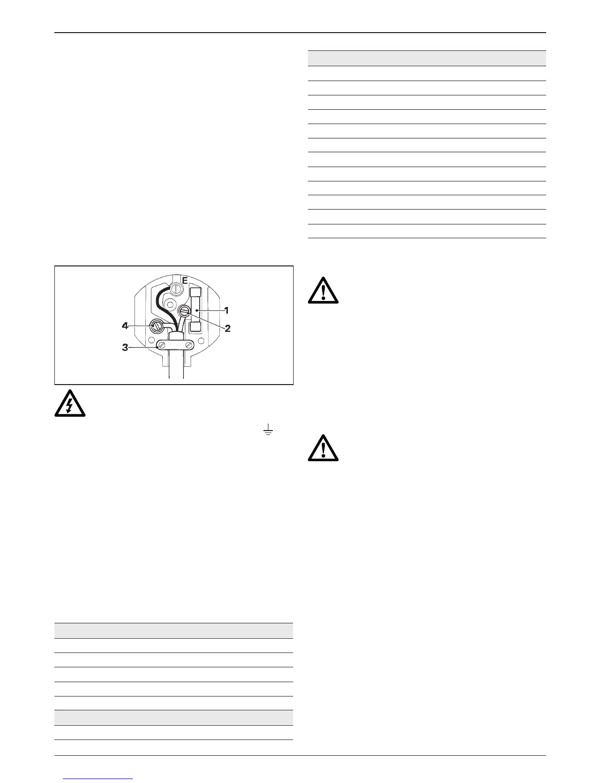
• Only fit 13 Amperes BS1363A approved plugs
fitted with the correctly rated fuse (1).
• The cable wire colours, or a letter, will be marked
at the connection points of most good quality
plugs. Attach the wires to their respective points
in the plug (see below). Brown is for Live (L) (2)
and Blue is for Neutral (N) (4).
• Before replacing the top cover of the mains plug
ensure that the cable restraint (3) is holding the
outer sheath of the cable firmly and that the two
leads are correctly fixed at the terminal screws.
Never use a light socket.
Never connect the live (L) or neutral (N)
wires to the earth pin marked E or .
For 115 V units with a power rating exceeding 1500 W,
we recommend to fit a plug to BS4343 standard.
Using an extension cable
If an extension cable is required, use an approved
extension cable suitable for the power input of this
tool (see technical data). The minimum conductor
size is 1.5 mm
2
.
When using a cable reel, always unwind the cable
completely.
Also refer to the table below.
Conductor size (mm
2
) Cable rating (Amperes)
0.75 6
1.00 10
1.50 15
2.50 20
4.00 25
Cable length (m)
7.5 15 25 30 45 60
Voltage Amperes Cable rating (Amperes)
115 0 - 2.0 6 6 6 6 6 10
2.1 - 3.4 6 6 6 6 15 15
3.5 - 5.0 6 6 10 15 20 20
5.1 - 7.0 10 10 15 20 20 25
7.1 - 12.0 15 15 20 25 25 -
12.1 - 20.0 20 20 25 - - -
230 0 - 2.0 6 6 6 6 6 6
2.1 - 3.4 6 6 6 6 6 6
3.5 - 5.0 6 6 6 6 10 15
5.1 - 7.0 10 10 10 10 15 15
7.1 - 12.0 15 15 15 15 20 20
12.1 - 20.0 20 20 20 20 25 -
Assembly and adjustment
Prior to assembly and adjustment always
unplug the tool.
Inserting and removing SDS-max
®
accessories
(fig. B1 & B2)
This machine uses SDS-max
®
chisels (refer to the
inset in fig. B2 for a cross-section of a chisel shank).
We recommend to use professional accessories only.
• Clean and grease the chisel shank.
Do not apply lubricant to the machine.
• Insert the chisel shank into the tool holder (6),
and press and turn the chisel slightly until the
sleeve snaps into position.
• Pull on the chisel to check if it is properly locked.
The hammering function requires the chisel to be
able to move axially several centimetres when
locked in the tool holder.
• To remove a chisel pull back the tool holder locking
sleeve (6) and pull the chisel out of the tool holder.
Indexing the chisel position (fig. C)
The chisel can be indexed and locked into 12
different positions.
• Insert the chisel as described above.
• Rotate the collar (5) in the direction of the arrow
until the chisel is in the desired position.
 Loading...