ENGLISH
8
Mode Selection (Fig. A)
The mode selection collar
6
can be used to select
the correct operating mode depending upon the
plannedapplication.
To select, rotate the collar until the desired symbol aligns
with thearrow.
Speed Selection (Fig. A)
The tool features two speed settings for greaterversatility.
NOTE: Do not change speeds when the tool is running.
Always allow the tool to come to a complete stop before
changingspeed.
1. To select speed 1 (higher torque setting), slide the
speed selector
7
back (away from the chuck).
2. To select speed 2 (lower torque setting), slide the speed
selector forward (towards the chuck).
If the tool does not change speeds, confirm that the speed
selection switch is completely engaged in the forward or
back position.
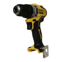
Installing a Bit or Accessory into a
Keyless Chuck (Fig. D)
WARNING: Do not attempt to tighten drill bits (or
any other accessory) by gripping the front part of the
chuck and turning the tool on. Damage to the chuck
and personal injury may result. Always lock off trigger
switch and disconnect tool from power source when
changingacces sories.
WARNING: Always ensure the bit is secure before
starting the tool. A loose bit may eject from tool
causing possible personalinjury.
To install a drill bit or other accessory:
1. Rotate the chuck sleeve
9
to open the teeth of
the keyless chuck
10
far enough to accept the
desiredaccessory.
2. Insert the accessory about 3/4" (19 mm) into the keyless
chuck and tighten securely by rotating the chuck sleeve.
NOTE: For maximumtightness, tighten the keyless
chuck with one hand on the chuck sleeve and one hand
holding thetool.
To remove a drill bit or other accessory:
• Rotate the sleeve far enough to open the teeth to
release the accessory.
Fig.D
9
10
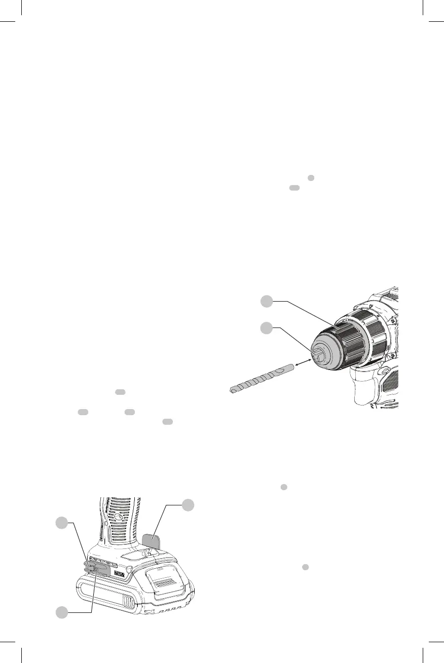
Belt Hook and Bit Clip
(Optional Accessory) (Fig. C)
WARNING: To reduce the risk of serious personal
injury, ONLY use the tool’s belt hook to hang
the tool from a work belt. DO NOT use the belt
hook for tethering or securing the tool to a person or
object during use. DO NOT suspend tool overhead or
suspend objects from the belthook.
WARNING: To reduce the risk of serious personal
injury, ensure the screw holding the belt hook
issecure.
IMPORTANT: When attaching or replacing the belt hook or
bit clip, use only the screw
11
that is provided. Be sure to
securely tighten thescrew.
The belt hook
12
and bit clip
13
can be attached to
either side of the tool using only the screw
11
provided, to
accommodate left- or right- handed users. If the belt hook
or bit clip is not desired at all, they can be removed from
thetool.
To move the belt hook or bit clip, remove the screw that
holds it in place then reassemble on the opposite side. Be
sure to securely tighten thescrew.
Fig.C
11
12
13
ASSEMBLY AND ADJUSTMENTS
WARNING: To reduce the risk of serious personal
injury, turn unit off and remove the battery pack
before making any adjustments or removing/
installing attachments or accessories. An
accidental start-up can causeinjury.
Intended Use
This tool is a professional power tool designed for drilling and
screwdriving.
DO NOT use under wet conditions or in presence of
flammable liquids orgases.
DO NOT let children come into contact with the tool.
Supervision is required when inexperienced operators use
thistool.
the charger securely using drywall screws (purchased
separately) at least 1" (25.4 mm) long, with a screw head
diameter of 0.28–0.35" (7–9mm), screwed into wood to an
optimal depth leaving approximately 7/32" (5.5 mm) of the
screw exposed. Align the slots on the back of the charger
with the exposed screws and fully engage them in theslots.
 Loading...