10
ENGLISH
Use only one hand to hold the tool as shown in FigureC. Do not
place your other hand over the airvents.
Proper Hand Position (Fig. C)
WARNING: To reduce the risk of serious personal injury,
ALWAYS use proper hand position asshown.
WARNING: To reduce the risk of serious personal
injury, ALWAYS hold securely in anticipation of a
suddenreaction.
OPERATION
Instructions for Use
WARNING: Always observe the safety instructions and
applicableregulations.
WARNING: To reduce the risk of serious personal
injury, turn tool off and disconnect battery pack
before making any adjustments or removing/
installing attachments or accessories. An accidental
start-up can causeinjury.
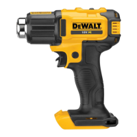
Air Temperature (Fig.A)
The Heat Gun has two temperature settings. Slide the air
temperature adjustment switch
3
forwards to select low heat
(L), or pull the switch backwards to select high heat (H).
Applications
The table below suggests settings for differentapplications.
Inserting and Removing the Battery Pack
from the Tool (Fig. B)
NOTE: Make sure your battery pack
7
is fullycharged.
To Install the Battery Pack into the Tool Handle
1. Align the battery pack
7
with the rails inside the tool’s
handle (Fig. B).
2. Slide it into the handle until the battery pack is firmly seated
in the tool and ensure that you hear the lock snap intoplace.
To Remove the Battery Pack from the Tool
1. Press the release button
6
and firmly pull the battery pack
out of the toolhandle.
2. Insert battery pack into the charger as described in the
charger section of thismanual.
Fuel Gauge Battery Packs (Fig. B)
Some
battery packs include a fuel gauge which
consists of three green LED lights that indicate the level of
charge remaining in the batterypack.
To actuate the fuel gauge, press and hold the fuel gauge
button
11
. A combination of the three green LED lights will
illuminate designating the level of charge left. When the level
of charge in the battery is below the usable limit, the fuel gauge
will not illuminate and the battery will need to berecharged.
NOTE: The fuel gauge is only an indication of the charge left on
the battery pack. It does not indicate tool functionality and is
subject to variation based on product components, temperature
and end-userapplication.
ASSEMBLY AND ADJUSTMENTS
WARNING: To reduce the risk of serious personal
injury, turn tool off and disconnect battery pack
before making any adjustments or removing/
installing attachments or accessories. An accidental
start-up can causeinjury.
WARNING: Use only
battery packs andchargers.
Setting Applications
Low • Drying paint and varnish
• Removing stickers
• Waxing and dewaxing
• Drying wet timber prior to filling
• Shrinking PVC wrapping and
insulation tubes
• Thawing frozen pipes
High • Welding plastics
• Bending plastic pipes and sheets
• Loosening rusted or tightly
fastened nuts and bolts
• Removing paint and lacquer
• Soldering plumbing joints
• Removing linoleum or vinyl
floor tiles
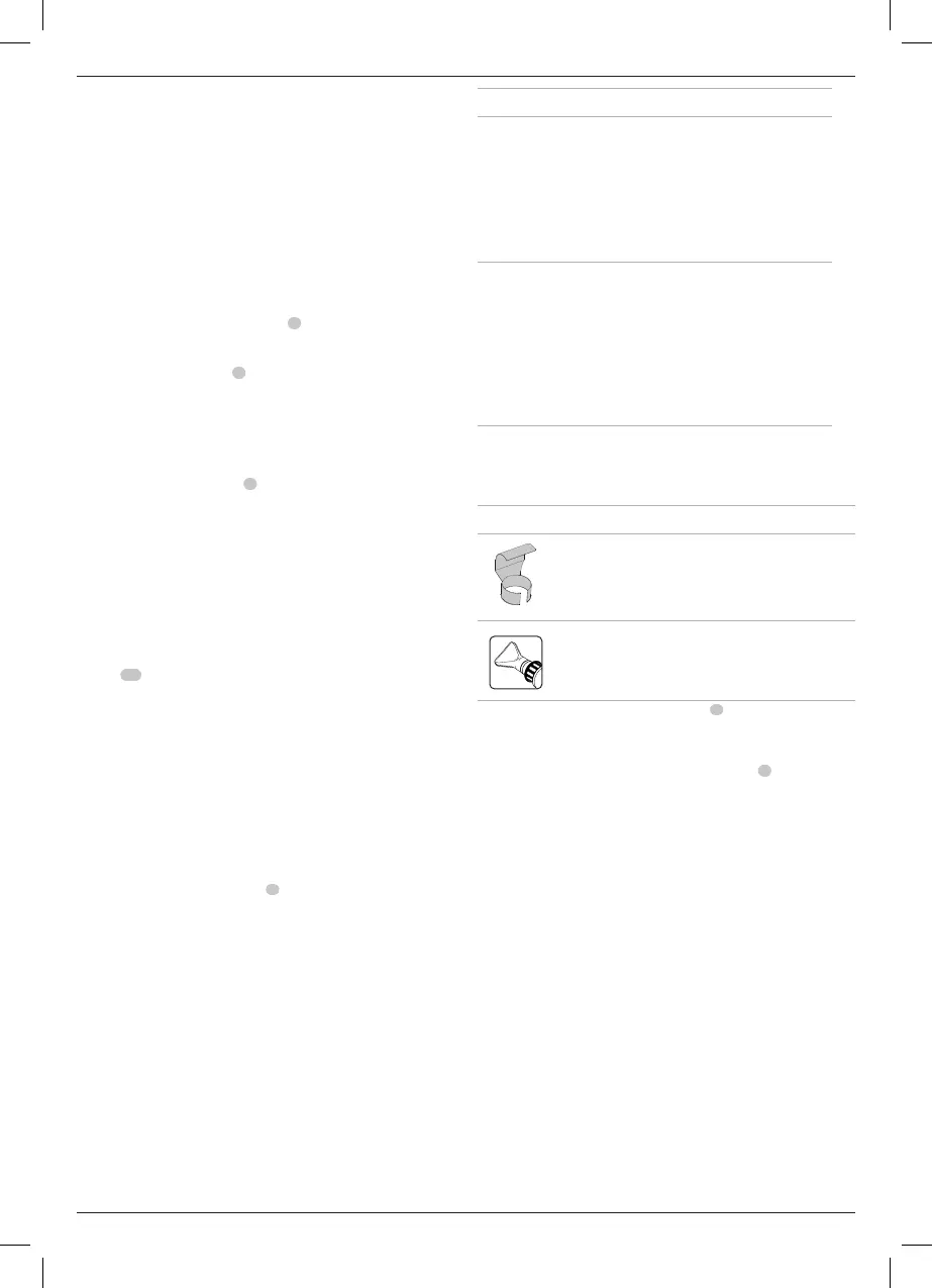
To Attach the Correct Accessory (Fig. A)
This tool is supplied with a set of accessories for
differentapplications.
Icon Description Purpose
Reflector nozzle or
hook nozzle
Heat shirnk wrap reflecting heat
around item. avoiding excess heat
burning or hurting surface behind
item being heated.
75 mm Fish tail
surface nozzle
Drying, removing paint, removing
vinyl or linoleum, thawing (heat
spread over wide area).
1. Make sure the on/off trigger switch
1
is in the off position
and the tool is disconnected from the power source. Ensure
the nozzle has cooleddown.
2. Place the desired accessory onto thenozzle
4
.
 Loading...