ENGLISH
9
operate. For maximum tool life, use variable speed only for
starting holes orfasteners.
NOTE: Continuous use in variable speed range is not
recommended. It may damage the switch and should
beavoided.
Forward/Reverse Control Button (Fig. A)
A forward/reverse control button
2
determines the
direction of the tool and also serves as a lock-offbutton.
To select forward rotation, release the trigger switch and
depress the forward/reverse control button on the right side
of thetool.
To select reverse, release the trigger switch and depress the
forward/reverse control button on the left side of thetool.
The center position of the control button locks the tool in
the off position. When changing the position of the control
button, be sure the trigger isreleased.
NOTE: The first time the tool is run after changing the
direction of rotation, you may hear a click on start up. This is
normal and does not indicate aproblem.
Quick-Release Chuck (Fig. A, D, E)
WARNING: Use only impact accessories. Non-impact
accessories may break and cause a hazardous
condition. Inspect accessory prior to use to ensure that
it con tains nocracks.
NOTE: The chuck accepts 1/4" (6.35 mm) hexaccessories.
Place the forward/reverse button
2
in the lock-
off (center) position or remove battery pack before
changingaccessories.
Fig. D Fig. E
4
3
3
4
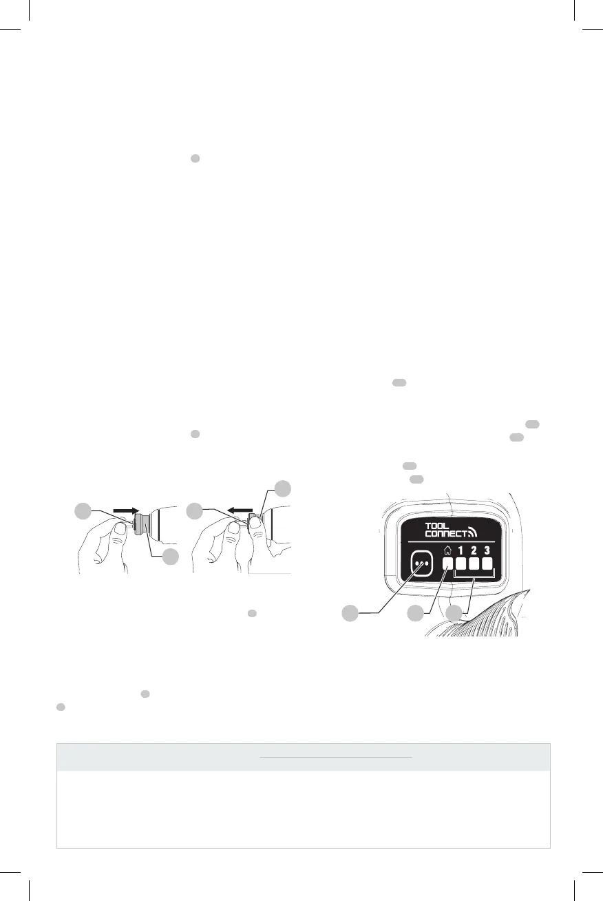
To install an accessory, fully insert the accessory. The
accessory is locked into place (Fig.D).
To remove an accessory, pull the chuck collar
3
away
from the front of the tool. Remove the accessory (Fig.E).
Worklights (Fig. A)
CAUTION: Do not stare into worklight. Serious eye
injury couldresult.
The three worklights
7
located around the chuck collar
3
are activated when the trigger switch is depressed.
In the factory preset mode, when the trigger is released,
the worklight will stay illuminated for up to 20 seconds. If
the trigger switch remains depressed, the worklights will
remain on. These settings can be customized using the Tool
Connect™ app. Refer to ModeSelector.
NOTE: The worklights are for lighting the immediate work
surface and are not intended to be used as aflashlight.
ASSEMBLY AND ADJUSTMENTS
WARNING: To reduce the risk of serious personal
injury, turn unit off and remove the battery pack
before making any adjustments or removing/
installing attachments or accessories. An
accidental start-up can causeinjury. Exception—Tool
Connect™ functions and mode adjustments require
battery to beinstalled.
Mode Selector (Fig. A, F)
WARNING: To reduce the risk of injury, remove
accessories from the tool chuck before using the
modeselector.
Your tool is equipped with a mode selector that
allows modes 1, 2, and 3 to be customized using the
Tool Connect™ app. Home settings are active when
the home indicator
12
is lit. The following 4 features
can becustomized. For more information, refer to
Table1below.
Once configured, pressing the mode selector button
11
on
the foot of the tool will cycle through the modes
13
.
If you are unsure of the current configuration, press the
mode selector button
11
to set the tool to the Home
setting (home indicator
12
is lit).
11
Fig. F
12 13
Tool Connect™
WARNING: To reduce the risk of injury, remove
accessories from the tool chuck before any Tool
Connect™interaction.
Table 1
Customizable Features Home
Factory Presets
Customizable RangeMode 1 Mode 2 Mode 3
Worklight brightness High High High High OFF–High
Worklight delay off 20 secs 20 secs 20 secs 20 secs 0–20 minutes
Maximum speed (RPM) 3250 1000 2800 3250 1000–3250
Precision Drive hesitation (seconds) Disabled 1 Disabled Disabled 0–1
 Loading...