ENGLISH
13
Wire cup brushes or wire wheels install directly on the
threaded spindle without the use of flanges. Use only wire
brushes or wheels provided with a threaded hub. These
accessories are available at extra cost from your local dealer
or authorised servicecenter.
1. Place the tool on a table, guardup.
2. Thread the wheel on the spindle byhand.
3. Depress spindle lock button
3
and use a wrench on the
hub of the wire wheel or brush to tighten thewheel.
4. To remove the wheel, reverse the aboveprocedure.
NOTICE: To reduce the risk of damage to the tool,
properly seat the wheel hub before turning the toolon.
Prior to Operation
• Install the guard and appropriate disc or wheel. Do not
use excessively worn discs orwheels.
• Be sure the backing flange and locking flange are
mounted correctly. Follow the instructions given in the
AccessoryChart.
• Make sure the disc or wheel rotates in the direction of
the arrows on the accessory and thetool.
• Do not use a damaged accessory. Before each use
inspect the accessory such as abrasive wheels for chips
and cracks, backing pad for cracks, tear or excess wear,
wire brush for loose or cracked wires. If power tool or
accessory is dropped, inspect for damage or install an
undamaged accessory. After inspecting and installing
an accessory, position yourself and bystanders away
from the plane of the rotating accessory and run the
power tool at maximum no-load speed for one minute.
Damaged accessories will normally break apart during
this testtime.
OPERATION
WARNING: To reduce the risk of serious personal
injury, turn unit off and remove the battery pack
before making any adjustments or removing/
installing attachments or accessories. An
accidental start-up can causeinjury.
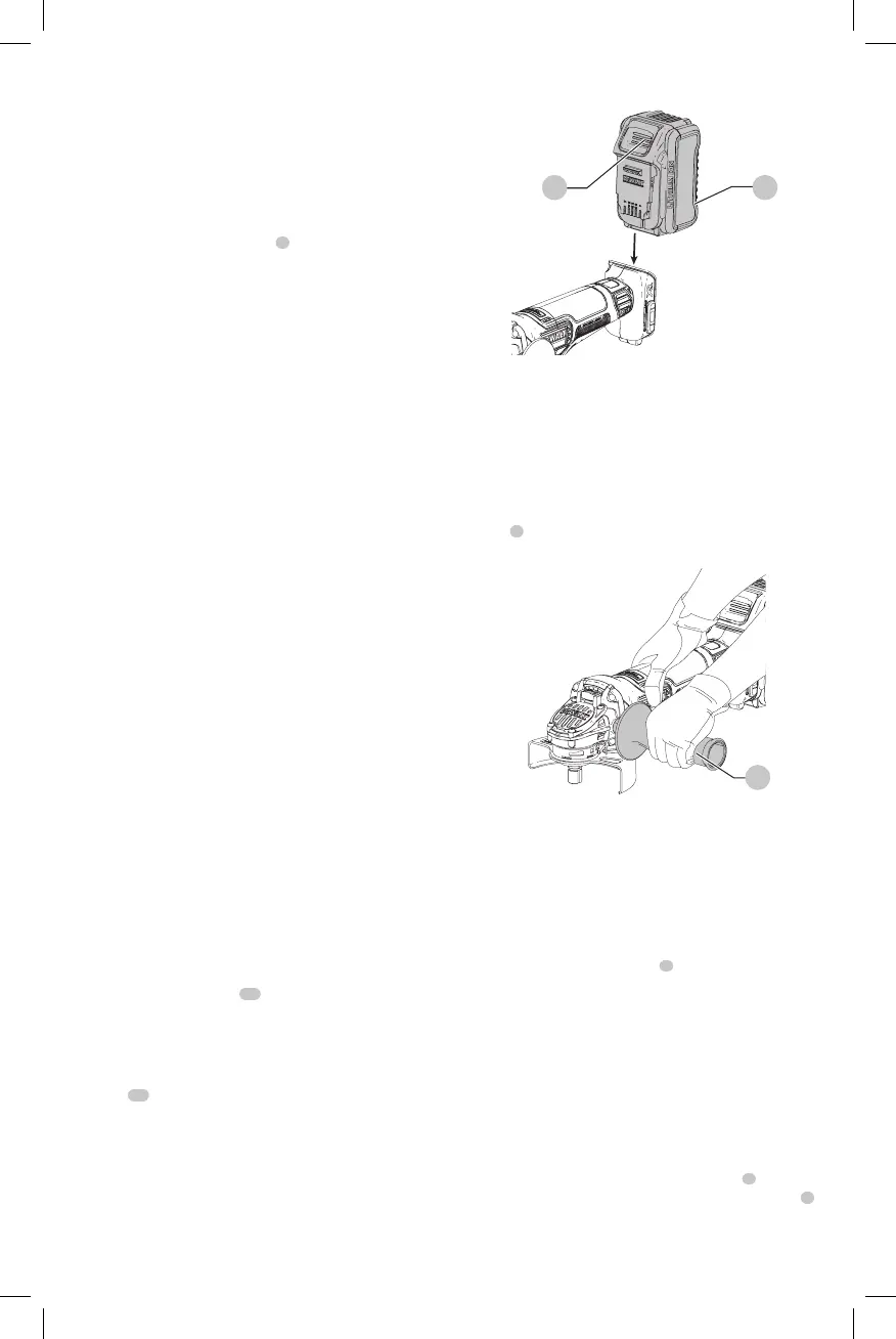
Installing and Removing the Battery Pack
(Fig. I)
NOTE: For best results, make sure your battery pack is
fullycharged.
To install the battery pack
10
into the tool handle, align the
battery pack with the rails inside the tool’s handle and slide
it into the handle until the battery pack is firmly seated in
the tool and ensure that it does notdisengage.
To remove the battery pack from the tool, press the release
button
11
and firmly pull the battery pack out of the tool
handle. Insert it into the charger as described in the charger
section of thismanual.
Fig. I
11 10
Proper Hand Position (Fig. J)
WARNING: To reduce the risk of serious personal injury,
ALWAYS use proper hand position asshown.
WARNING: To reduce the risk of serious personal
injury, ALWAYS hold securely in anticipation of a
suddenreaction.
Proper hand position requires one hand on the side
handle
5
, with the other hand on the body of the tool, as
shown in FigureJ.
Fig. J
5
Paddle Switch (Fig. A)
CAUTION: Hold the side handle and body of the tool
firmly to maintain control of the tool at start up and
during use and until the wheel or accessory stops
rotating. Make sure the wheel has come to a complete
stop be fore laying the tooldown.
CAUTION: Before inserting the battery, depress and
release the paddle switch
1
once to ensure that the
switch is off. Depress and release the paddle switch
as described below after any interruption in power
supply to the tool, such as motor overload, pinch,
stall or bind-up event, or any other unexpected
toolshutdown.
NOTE: To reduce unexpected tool movement, do not
switch the tool on or off while under load conditions. Allow
the grinder to run up to full speed before touching the work
surface. Lift the tool from the surface before turning the tool
off. Allow the tool to stop rotating before putting itdown.
1. To turn the tool on, push the lock-off lever
2
toward
the back of the tool, then depress the paddle switch
1
.
The tool will run while the switch isdepressed.
2. Turn the tool off by releasing the paddleswitch.
 Loading...