11
ENGLISH
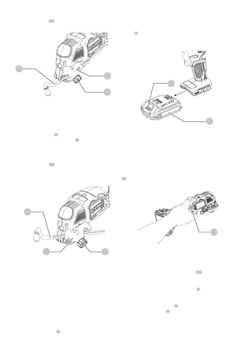
3. Secure the guide in place by turning the depth/cut
adjustment knob
19
clockwise. To release the guide,
turn the depth/cut adjustment knob counterclockwise.
Fig.G
6
19
7
Cut Guide (Fig. H)
Optional Accessory
This feature allows you to more accurately track a marked
cut line.
1. Insert the guide arm
7
into the slots on the left and
right sides of the cut guide block
6
.
2. Adjust the length of the guide by pulling out or pushing
inward to achieve the desired length.
3. Secure the guide in place by turning the depth/cut
adjustment knob
19
clockwise. To release the guide,
turn the depth/cut adjustment knob counterclockwise.
NOTE: The guide arm can also be placed in the guard
assembly vertically in order to set the height of a cut.
Fig.H
19
6
7
OPERATION
WARNING: To reduce the risk of serious personal
injury, turn unit off and remove the battery pack
before making any adjustments or removing/
installing attachments or accessories. An
accidental start-up can causeinjury..
Installing and Removing the Battery Pack
(Fig. I)
NOTE: For best results, make sure your battery pack is
fullycharged.
To install the battery pack
8
into the tool handle, align the
battery pack with the rails inside the tool’s handle and slide
it into the handle until the battery pack is firmly seated in
the tool and ensure that it does notdisengage.
To remove the battery pack from the tool, press the release
button
9
and firmly pull the battery pack out of the tool
handle. Insert it into the charger as described in the charger
section of thismanual
Fig.I
9
8
Proper Hand Position (Fig. J)
WARNING: To reduce the risk of serious personal
injury, ALWAYS use proper hand position as shown.
WARNING: To reduce the risk of serious personal
injury, ALWAYS hold securely in anticipation of a
suddenreaction.
Proper hand position requires one hand on the main handle
11
.
Fig.J
11
Mode Selector (Fig. A)
DCS356
Your tool is equipped with a mode selector
10
which
allows you to select one of the three modes. Select the
mode based on the application and control the speed of the
tool using the variable speed trigger switch
1
.
Lock On/Off Button (Fig. A)
Engage the lock on/off button
4
by pushing it to the left
or right. When the trigger
1
is not depressed, pushing the
button fully to either side until it snaps into place will lock
the trigger and disable it from being depressed. Placing
the button in the center position allows the trigger to
operatenormally.
 Loading...