1
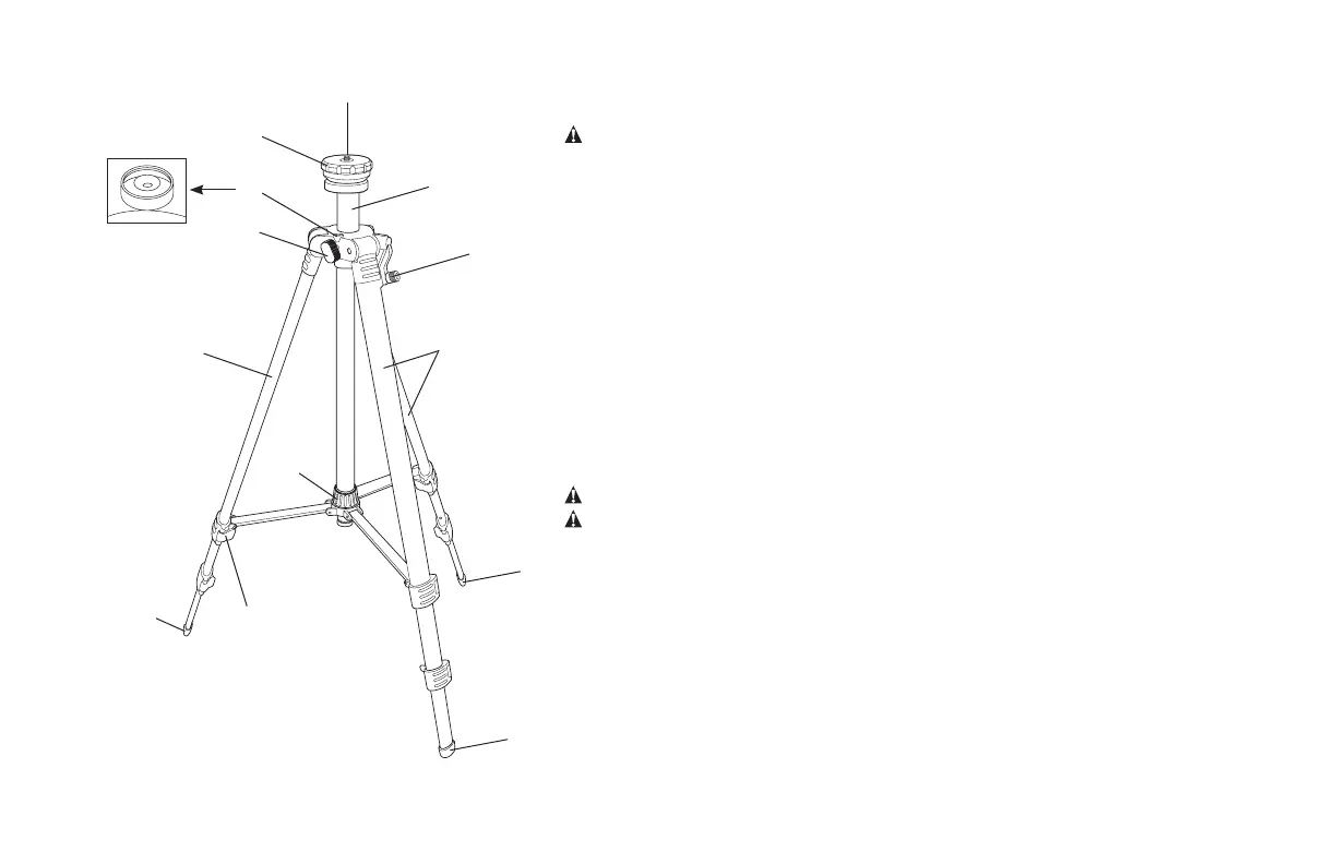
FIG. 1
E
A
B
D
E
F
C
C
I
J
E
H
G
DESCRIPTION (FIG. 1)
WARNING: Never modify the tripod or any part of it. Damage or personal injury
could result.
A. Rotary head mount F. Mounting thread
B. Quick-adjust latch G. Locking collar
C. Legs H. Elevator column
D. Elevator crank handle I. Elevator lock knob
E. Foot J. Bubble level
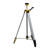
INTENDED USE
Your tripod has been designed to extend the capabilities of your laser. The tripod
helps to position the laser on rough, out-of-level surfaces. The tripod can be used
both indoors and outdoors.
DO NOT let children come into contact with the attachment or laser. Supervision is
required when inexperienced operators use this attachment.
OPERATION
Instructions for Use
WARNING: Always observe the safety instructions and applicable regulations.
WARNING: Refer to the laser manual to be used with this attachment.
Bubble Level
Use the bubble level (J), located under the rotary head mount (A), to ensure the
tripod is level.
Tripod Setup
1. Spread the legs (C) apart to install the tripod in upright position.
2. Tighten the locking collar (G).
3. Adjust the legs (C) if required so that each of the feet (E) is firmly touching the
ground.
4. Mount the laser on the tripod.
 Loading...