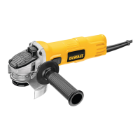
ATTACHING SIDE HANDLE (FIG. 2)
The side handle (C) can be fitted to either side
of the gear case in the threaded holes, as
shown. Before using the tool, check that the
handle is tightened se cure ly. Use a wrench to
firmly tighten the side handle.
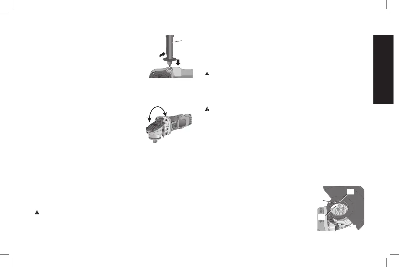
Rotating the Gear Case
(Fig. 3)
1. Remove the four corner screws attaching the gear case to motor
housing.
2. Without separating the gear case from
motor housing, rotate the gear case
head to desired position.
NOTE: If the gear case and motor
housing become separated by more than
1/8" (3.17 mm), the tool must be serviced
and re-assembled by a D
WALT service
center. Failure to have the tool serviced
may cause brush, motor and bearing
failure.
3. Reinstall screws to attach the gear case to the motor housing.
Tighten screws to 18 in.-lbs. torque. Overtightening could cause
screws to strip.
Accessories and Attachments
It is important to choose the correct guards, backing pads and
flanges to use with grinder accessories. See the Accessories Chart
for information on choosing the correct accessories.
WARNING: Accessories must be rated for at least the speed
recom mended on the tool warning label. Wheels and other
accessories running over rated accessory speed may burst and
C
FIG. 2
FIG. 3
90˚
90˚
cause injury. Threaded accessories must have a 5/8"–11 hub. Every
unthreaded accessory must have a 7/8" arbor hole. If it does not, it
may have been designed for a circular saw and should not be used.
Use only the accessories shown in the Accessories Chart of this
manual. Accessory ratings must be above listed minimum wheel
speed as shown on tool nameplate.
WARNING: Handle and store all abrasive wheels carefully to
prevent damage from thermal shock, heat, mechanical damage, etc.
Store in a dry protected area free from high humidity, freezing
temperatures or extreme temperature changes.
Mounting Guard
CAUTION: Guards must be used with all grinding wheels,
cutting wheels, sanding flap discs, wire brushes, and wire
wheels. The tool may be used without a guard only when sanding
with conventional sanding discs. A Type 27 guard (intended for use
with depressed center grinding wheels [Type 27 and Type29], sanding
flap discs, wire wheels and wire cup brushes) is available at extra cost
from your local dealer or authorized service center. Grinding and
cutting with wheels other than Type 27 and 29 require different
accessory guards not included with tool. A Type 1 guard is provided
for use with the Type 1 wheel. Mounting instructions for accessory
guards are shown below and are also included in the accessory
package.
MOUNTING AND REMOVING (TYPE 27)
ONE-TOUCH™ GUARD (FIG. 4, 5)
NOTE: If your grinder is supplied with a
L
K
FIG. 4
N
M
keyless ONE TOUCH™ guard, ensure the
screw, lever and spring are fitted correctly
before mounting the guard.
1. Press and hold the guard release lever (K).
9
 Loading...