5
ENGLISH
Fig. C
36
23
16
Fig. D
24
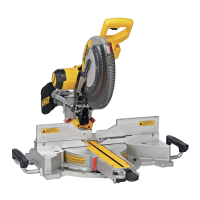
6. Remove the blade screw
23
, outer blade clamp
25
, and blade
26
. The inner blade
clamp
27
, and if used, the 1" (25.4 mm) blade adapter, may be left on thespindle.
NOTE: For blades with a blade hole of 5/8" (15.88 mm), the 1" (25.4 mm) blade adapter is
notused.
Fig. E
23
25
26
27
Installing a Blade
1. Unplug thesaw.
2. With the arm raised, the lower guard held open and the guard bracket raised, place the blade
on the spindle, onto the blade adapter [if using a blade with a 1" (25.4 mm) diameter blade
hole] and against the inner blade clamp with the teeth at the bottom of the blade pointing
toward the back of thesaw.
3. Assemble the outer blade clamp onto thespindle.
4. Install the blade screw
23
and, engaging the spindle lock, tighten the screw firmly with the
6mm hex wrench provided. (Turn counterclockwise, left-hand threads.)
NOTE: When using blades with a 5/8" (15.88 mm) diameter blade hole, the blade adapter will
not be used and should be stored in a safe place for futureuse.
5. Return the guard bracket to its original position and firmly tighten the guard bracket
screw
36
to hold bracket inplace.
WARNING:
• The guard bracket must be returned to its original position and the screw
tightened before activating thesaw.
• Failure to do so may allow the guard to contact the spinning saw blade resulting
in damage to the saw and severe personalinjury.
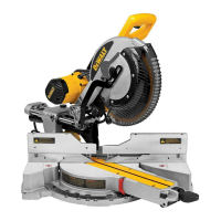
Mitre Scale Adjustment (Fig. F)
Place a square against the saw’s fence and blade. (Do not touch the tips of the blade teeth with
the square. To do so will cause an inaccurate measurement.) Unlock mitre lock knob
5
and
swing the mitre arm until the mitre detent latch locks it at the 0˚ mitre position. Do not lock
mitre lock knob. If the saw blade is not exactly perpendicular to the base fence
18
, loosen the
three mitre scale screws
8
that hold the mitre scale
7
to the base and move the scale/mitre arm
assembly left or right until the blade is perpendicular to the fence, as measured with the square.
Retighten the three screws. Pay no attention to the reading of the mitre pointer at thispoint.
Fig. F
5
7
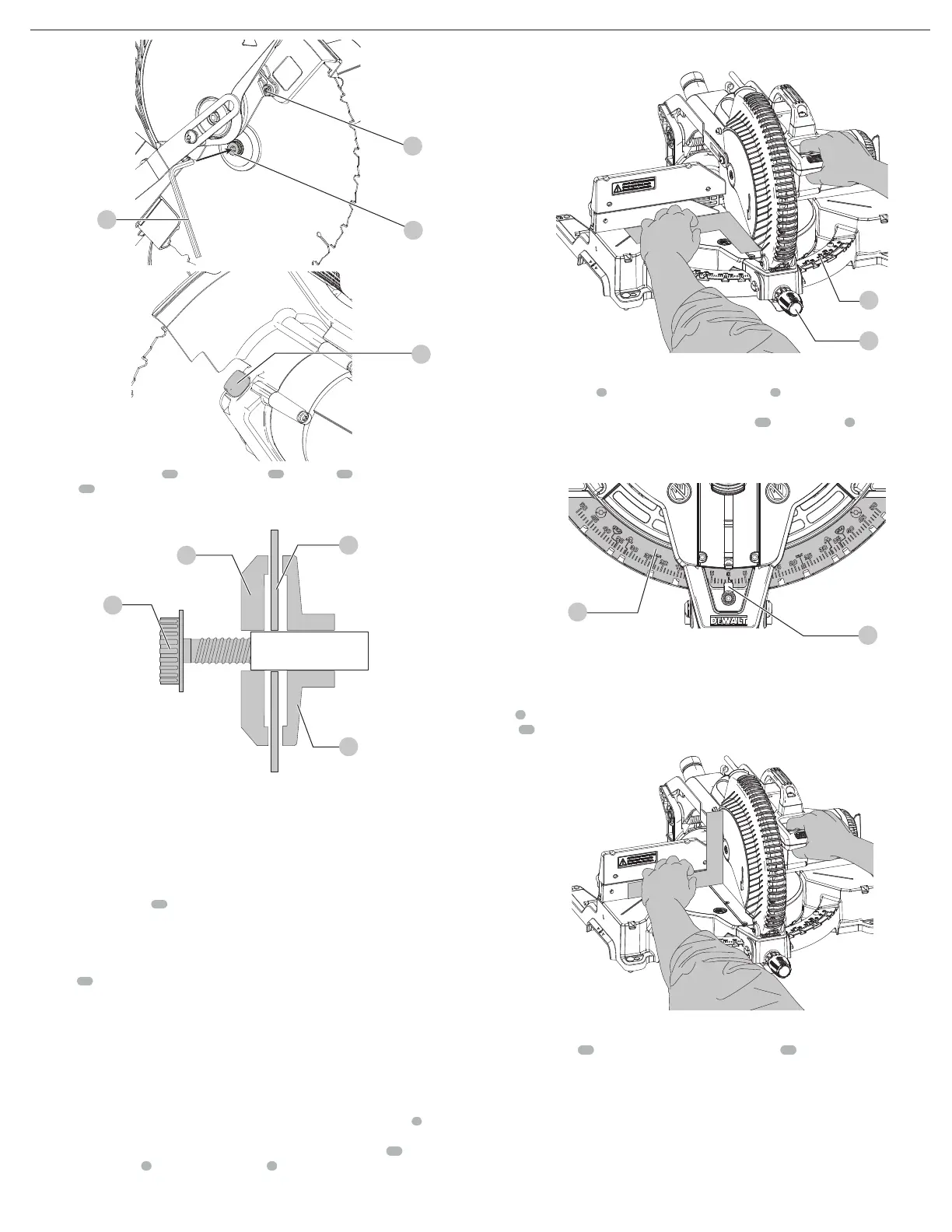
Mitre Pointer Adjustment (Fig. A, F, G)
Unlock mitre lock knob
5
and squeeze the mitre detent latch
6
to move the mitre arm to the
zero position. Unlock the mitre lock knob to allow the mitre detent latch to snap into place as
you rotate the mitre arm toward zero. Observe the pointer
28
and mitre scale
7
through the
viewing opening shown in FigureG. If the pointer does not indicate exactly zero, loosen the
pointer screw, adjust the pointer to 0˚ andretighten.
Fig. G
7
28
Bevel Square to Table (Fig. A, H)
To align the blade square to the rotary table, lock the arm in the down position. Place a square
against the blade taking care to not have the square on top of a tooth. Loosen the bevel lock
knob
5
and ensure the arm is firmly against the 0° bevel stop. Move the 0° bevel stop adjusting
screw
19
as necessary so that the blade is at 0° bevel to the table. Ensure the bevel override
levers are pushed inward to obtain an accurateadjustment.
Fig. H
Bevel Pointer (Fig. I)
If the bevel pointer
29
does not indicate zero, loosen the screw
30
that holds it in place and
move the pointer as necessary. Do not remove the steel plate in front of the bevel pointer. This
plate prevents wood resin from accumulating on the bevel scale duringuse.
 Loading...