6
ENGLISH
Fig. H
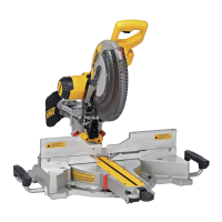
Bevel Pointer (Fig. I)
If the bevel pointer
29
does not indicate zero, loosen the screw
30
that holds it in place and
move the pointer as necessary. Do not remove the steel plate in front of the bevel pointer. This
plate prevents wood resin from accumulating on the bevel scale duringuse.
29
30
Fig. I
Adjusting the Bevel Stop to 45° Left (Fig. A, I, J)
NOTE: Adjust the 45° bevel angle only after performing the 0° bevel angle and pointer
adjustment. Ensure the 45° bevel override levers
20
are pushed inward to obtain an
accurateadjustment.
To adjust the left 45° bevel stop, first loosen the bevel lock knob
11
and tilt the head to the left.
If the bevel pointer
29
does not indicate exactly 45°, turn the left bevel stop screw until the
pointer reads45°.
Fig. J
11
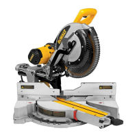
Fence Adjustment (Fig. K)
WARNING: To reduce the risk of serious personal injury, turn off the tool and
disconnect it from the power source before attempting to move it, change
accessories or make anyadjustments.
In order that the saw can bevel to a full 48° left, the fences can be adjusted to provide clearance.
To adjust a fence, loosen the fence lock knob
14
, and slide the fence outward. Make a dry run
with the saw turned off and check for clearance. Adjust the fence to be as close to the blade as
practical to provide max imum workpiece support, without interfering with arm up and down
movement. Tighten knob securely. When the bevel operations are complete, don’t forget to
relocate thefence.
NOTE: The guide groove of the fences can become clogged with sawdust. If the guide groove
becomes clogged, use a stick, low pressure air or a vacuum toclear.
Fig. K
14
Automatic Electric Brake
Your saw is equipped with an automatic electric blade brake which stops the saw blade within 5
seconds of trigger release. This is notadjustable.
On occasion, there may be a delay after trigger release to brake engagement. On rare occasions,
the brake may not engage at all and the blade will coast to astop.
If a delay or “skipping” occurs, turn the saw on and off 4 or 5 times. If the condition persists, have
the tool serviced by an authorized
WALT servicecenter.
Always be sure the blade has stopped before removing it from the kerf plate. The brake is not a
substitute for guards or for ensuring your own safety by giving the saw your completeattention.
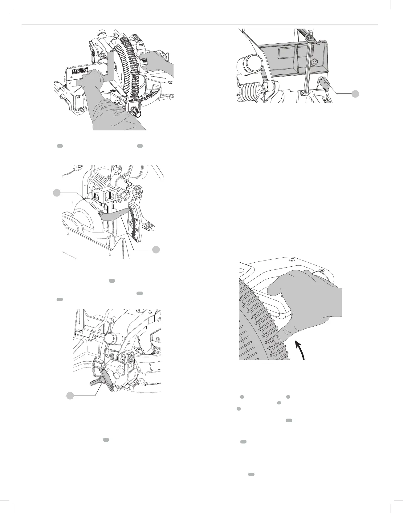
Guard Actuation and Visibility (Fig. L)
CAUTION: Pinch Hazard. To reduce the risk of injury, keep thumb underneath the handle
when pulling the handle down. The lower guard will move up as the handle is pulled down
which could causepinching.
The blade guard on your saw has been designed to automatically raise when the arm is brought
down and to lower over the blade when the arm israised.
The guard can be raised by hand when installing or removing saw blades or for inspection of the
saw. NEVER RAISE THE BLADE GUARD MANUALLY UN LESS THE SAW IS TURNEDOFF.
NOTE: Certain special cuts of large material will require that you manually raise the guard. The
front section of the guard is louvered for visibility while cutting. Although the louvers dramatically
reduce flying debris, there are openings in the guard and safety glasses should be worn at all
times. Refer to Cutting Large Material under SpecialCuts.
Fig. L
Controls
Your compound miter saw has several main controls, which will be discussed briefly here. For
more information on these controls, see the respective sections later in themanual.
Miter Control (Fig. A)
The miter lock knob
5
and miter detent latch
6
allow you to miter your saw 50° left and right.
To miter the saw, unlock miter lock knob
5
by rotating the knob counterclockwise, squeeze the
miter detent latch
6
and set the miter angle desired on the miter scale. Lock miter lock knob by
rotating clockwise until tight. Override the miter detent latch by unlocking the miter lock knob
and pushing the miter detent override switch
22
downward. To exit the override, push the miter
detent override switchupward.
Bevel Lock (Fig. J)
The bevel lock knob
11
allows you to bevel the saw 48° left and 3° to the right. To loosen the
handle and adjust the bevel setting, turn the handle counter clock wise, the saw head bevels easily
to the left. To tighten, turn the handle clockwise. Bevel degree markings are on the bottom front
of the saw arm (Fig.H).
0°/45° Bevel Stop Overrides (Fig. A)
The bevel stop overrides
20
are held secure with their attachment screw to prevent inadvertent
movement. Use the bit on the blade wrench to loosen the attachment screw. This allows the
 Loading...