10
ENGLISH
Fig. U
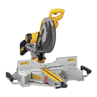
Cutting Base Molding up to 6.5" (165 mm) Vertically Against the
Fence (Fig. V)
Position molding as shown in FigureV.
All cuts made with the back of the molding against the fence and bottom of the molding against
thebase.
Inside corner Outside corner
Left side
1. Miter left 45°
2. Save left side of cut
1. Miter right 45°
2. Save right side of cut
Right side
1. Miter right 45°
2. Save right side of cut
1. Miter left 45°
2. Save right side of cut
Material up to 6.5"(165mm) can be cut as describedabove.
Cutting Crown Molding
Your miter saw is better suited to the task of cutting crown molding than any tool made. In order
to fit properly, crown molding must be compound mitered with extremeaccuracy.
The two flat surfaces on a given piece of crown molding are at angles that, when added together,
equal exactly 90°. Most, but not all, crown molding has a top rear angle (the section that fits flat
against the ceiling) of 52° and a bottom rear angle (the part that fits flat against the wall) of38°.
Your miter saw has special pre-set miter latch points at 31.6° left and right for cutting crown
molding at the proper angle and bevel stop pawls at 33.9° left and right. There is also a mark on
the bevel scale at 33.9°.
The Bevel Symbol/Miter Symbol chart gives the proper settings for cutting crown molding. (The
numbers for the miter and bevel settings are very precise and are not easy to accurately set on
your saw.) Since most rooms do not have angles of precisely 90°, you will have to fine tune your
settingsanyway.
PRETESTING WITH SCRAP MATERIAL IS EXTREMELY IMPORTANT!
Instructions for Cutting Crown Molding Laying Flat and Using
the Compound Features (Fig. A, V)
1. Molding laying with broad back surface down flat on saw table
38
.
Fig. V
10
38
2. For standard U.S. crown molding with a 52°/38° spring angle, match the following semi-circle
symbols on your saws bevel and miter scales per the chartbelow.
BEVEL SYMBOL MITER SYMBOL
TYPE OF CUT MITER ANGLE BEVEL ANGLE
Left side, Inside corner 31.6° right 33.9° left
Right side, Inside corner 31.6° right 33.9° right
Left side, Outside corner 31.6° left 33.9° right
Right side, Outside corner 31.6° right 33.9° left
For non-standard crown molding with a 45° spring angle, match the following triangle
symbols on your saws bevel and miter scales per the chartbelow.
BEVEL SYMBOL MITER SYMBOL
TYPE OF CUT MITER ANGLE BEVEL ANGLE
Left side, Inside corner 35.3° right 30° left
Right side, Inside corner 35.3° right 30° right
Left side, Outside corner 35.3° left 30° right
Right side, Outside corner 35.3° right 30° left
When setting bevel and miter angles for all compound miters, remember that:
The angles presented for crown moldings are very precise and difficult to set exactly. Since they
can easily shift slightly and very few rooms have exactly square corners, all settings should be tested
on scrapmolding.
PRETESTING WITH SCRAP MATERIAL IS EXTREMELY IMPORTANT!
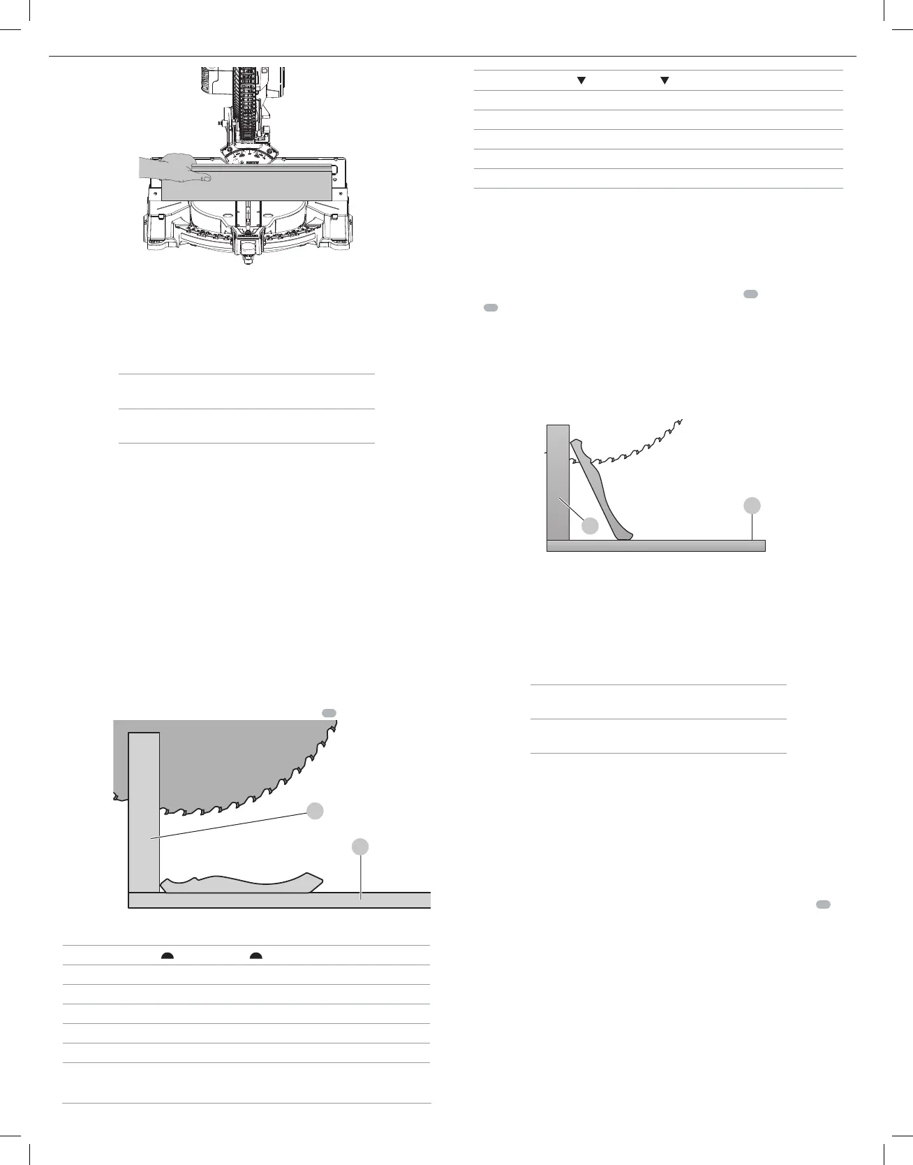
Alternative Method for Cutting Crown Molding (Fig. W)
Place the molding on the table at an angle between the sliding fence
10
and the saw
table
38
, as shown in FigureW. Use of the crown molding fence accessory (DW7084) is highly
recommended because of its degree of accuracy and convenience. The crown molding fence
accessory is available for purchase from your localdealer.
The advantage to cutting crown molding using this method is that no bevel cut is required.
Minute changes in the miter angle can be made without affecting the bevel angle. This way,
when corners other than 90° are encountered, the saw can be quickly and easily adjusted for
them. Use the crown molding fence accessory to maintain the angle at which the molding will
be on thewall.
Fig. W
38
10
Instructions for Cutting Crown Molding Angled Between the
Fence and Base of the Saw for All Cuts
1. Angle the molding so the bottom of the molding (part which goes against the wall when
installed) is against the fence and the top of the molding is resting on the base of the saw, as
shown in FigureW.
2. The angled “flats” on the back of the molding must rest squarely on the fence and base of
thesaw.
Inside corner Outside corner
Left side
1. Miter right 45°
2. Save right side of cut
1. Miter left 45°
2. Save right side of cut
Right side
1. Miter left 45°
2. Save left side of cut
1. Miter right 45°
2. Save left side of cut
Special Cuts
NEVER MAKE ANY CUT UNLESS THE MATERIAL IS SECURED ON THE TABLE AND AGAINST
THEFENCE.
Aluminum Cutting (Fig. A, X, Y)
ALWAYS USE THE APPROPRIATE SAW BLADE MADE ESPECIALLY FOR CUTTING ALUMINUM. These
are available at your local
retailer or
service center. Certain workpieces, due to
their size, shape or surface finish, may require the use of a clamp or fixture to prevent movement
during the cut. Position the material so that you will be cutting the thinnest cross section, as
shown in FigureX. FigureY illustrates the wrong way to cut these extrusions. Use a stick wax
cutting lubricant when cutting aluminum. Apply the stick wax directly to the saw blade
26
before cutting. Never apply stick wax to a movingblade.
The wax, available at most hardware stores and industrial mill supply houses, provides proper
lubrication and keeps chips from adhering to theblade.
Be sure to properly secureworkpiece.
 Loading...