ENGLISH
10
12
13
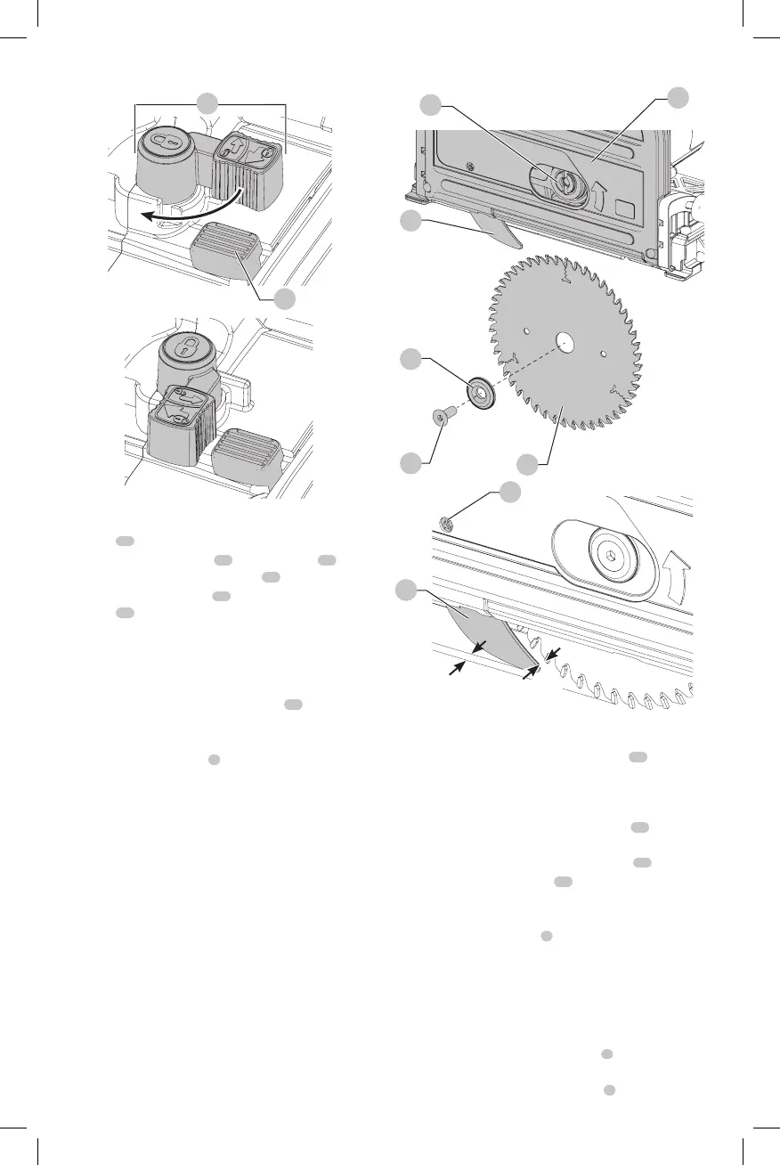
Fig. D
6. Use the hex wrench to turn the blade clamping
screw
24
counter-clockwise toremove.
7. Remove the outer flange
25
and used blade
10
. Place
the new blade on the inner flange
26
.
8. Replace the outer flange
25
and blade clamping
screw
24
. Turn the screw clockwise byhand.
NOTE: The direction of rotation of the saw blade and the
rotation of the track saw MUST be thesame.
9. Tighten the blade clamping screw firmly using the
hexwrench.
10. Release and turn the spindle lock lever
13
counter-
clockwise until itstops.
11. Move the track saw back to topposition.
12. Push the plunge trigger
1
forward, to take the saw out
of blade changemode.
Fig. E
24
25
21
26
10
23
5/64”-1/8”
(2–3 mm)
22
21
5/64”-1/8”
(2–3 mm)
Adjusting the Riving Knife (Fig. A1, D, E)
For the correct adjustment of the riving knife
21
, refer
to FigureE. Adjust the clearance of the riving knife after
changing the saw blade or whenevernecessary.
1. Follow Changing the Saw Blade steps 1–5.
2. Loosen the riving knife adjustment screw
22
with a hex
wrench and set the riving knife as shown in FigureE.
3. Tighten the riving knife adjustment screw
22
.
4. Turn the spindle lock lever
13
counter-clockwise until
itstops.
5. Move the track saw back to topposition.
6. Push the plunge trigger
1
forward, to take the saw out
of blade changemode.
Depth of Cut Adjustment (Fig. F)
The cutting depth can be set at 0–2.3” (0–59 mm) without
guide rail attached; with the guide rail attached: 0–2.2”
(0–55 mm).
1. Loosen the depth adjustment knob
8
and move the
pointer to obtain the correct depth ofcut.
2. Tighten the depth adjustment knob
8
.
 Loading...