ENGLISH
8
DO NOT let children come into contact with the tool.
Supervision is required when inexperienced operators use
thistool.
ASSEMBLY AND ADJUSTMENTS
WARNING: To reduce the risk of serious personal
injury, turn unit off and remove the battery pack
before making any adjustments or removing/
installing attachments or accessories. An
accidental start-up can causeinjury.
Attaching Sanding Discs (Fig. D)
Your sander is designed to use 5" (127 mm) sanding discs
9
with an 8-hole dust extraction pattern. Sanding discs for the
DCW210 attach with hook andloop.
The recommended DWE64233 sanding discs are available
at extra cost from your local dealer or authorized
servicecenter.
To Attach Sanding Disc to the Sanding
Pad (Fig. D)
1. Turn the sander over so that the sanding pad
6
is
facingupward.
2. Clean the dust from the sanding pad
6
face.
3. Hold the pad with one hand to keep it fromrotating.
4. With the other hand, align the holes and place the
disc
9
directly on top of thepad.
NOTE: These sanders are not to be used in drywall
applications. Using a sanding screen (e.g., screen used for
sanding drywall) directly on the hook and loop pad will not
hold and will damage the hooks on the pad. The hooks on
the pad will wear very rapidly if left in contact with the work
surface while the tool isoperating.
Fig. D
9 6
Switch (Fig. A)
To turn the unit on, depress the side of the dust-protected
switch
1
that corresponds to the symbol “I”. To turn the
tool off, depress the side of the switch that corresponds to
the symbol “O”.
Speed Control Dial (Fig. A)
The speed control dial
2
, shown in FigureA, allows you
to increase or decrease speed from 8000–12000 Orbits Per
Minute. The optimal speed setting for each application is
very much dependent on personal preference. Generally,
you will want to use a higher setting on harder materials
and a lower setting on softer materials. Material removal
rate increases as speedincreases.
Dust Extraction (Fig. E, H)
Your sander has two dust extraction methods: a built-in
dust port
3
which allows either the supplied dust bag
4
or a shop vacuum system to be connected; and a dust skirt
(
11
, Fig.H). The built-in dust port utilizes the
AirLock connection making it compatible with the
dustextractors.
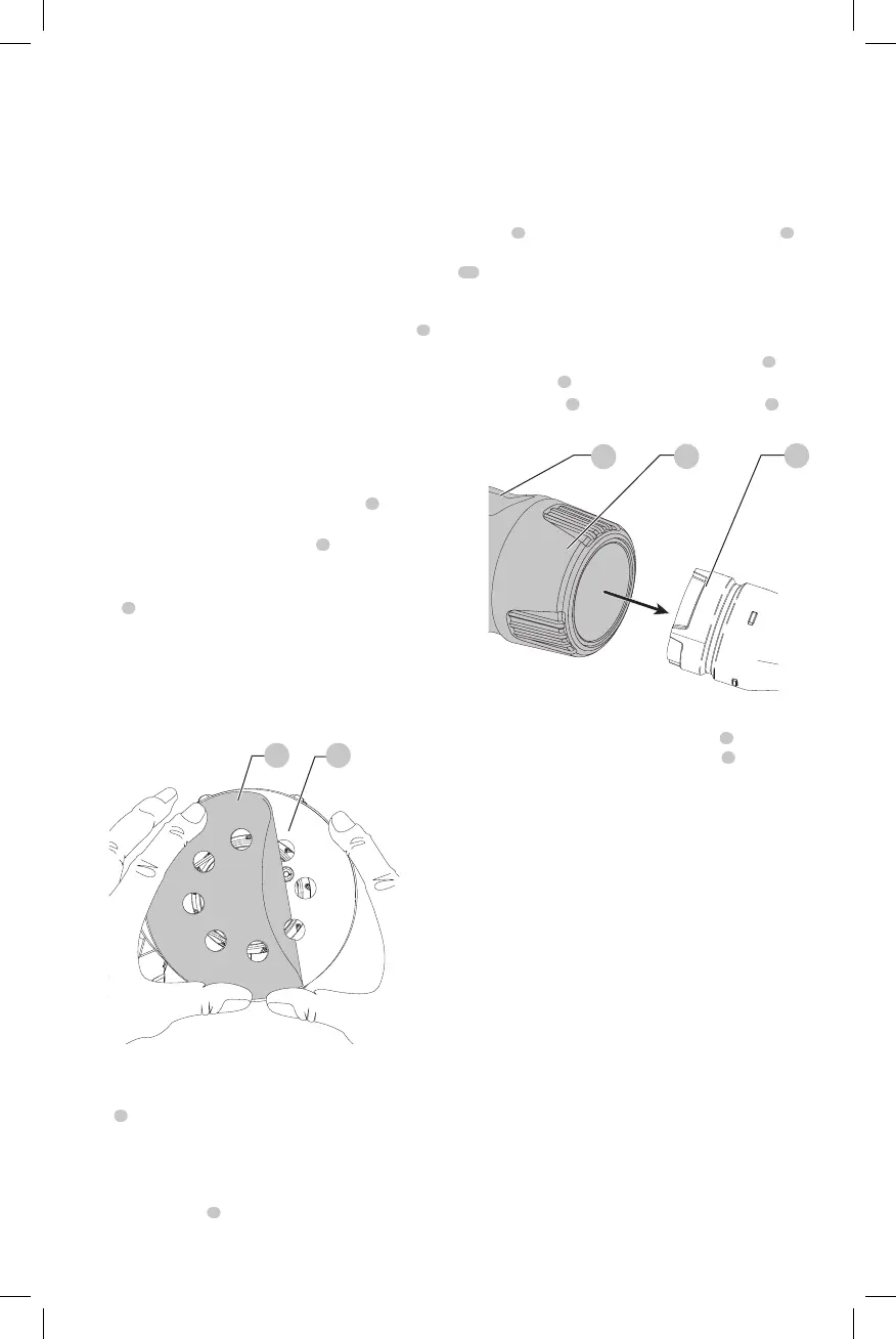
To Attach the Dust Bag (Fig. E)
1. While holding the sander, fit the dust bag collar
5
to
the dust port
3
as shown in FigureE.
2. Turn the collar
5
clockwise to lock the dust bag
4
inplace.
Fig. E
3
5
4
To Empty the Dust Bag (Fig. E)
1. While holding the sander, turn the collar
5
counterclockwise to unlock the dust bag
4
.
2. Remove dust bag from the sander and gently shake or
tap the dust bag toempty.
3. Reattach the dust bag back onto the dust port and lock
into place by turning the dust bag collarclockwise.
You may notice that all the dust will not come free from
the bag. This will not affect sanding performance but will
reduce the sander’s dust collection efficiency. To restore
your sander’s dust collection efficiency, depress the spring
inside the dust bag when you are emptying it and tap it on
the side of the trash can or dustreceptacle.
CAUTION: Never operate this sander unless a
dust collector is in place. Sanding dust exhaust may
create a breathinghazard.
OPERATION
WARNING: To reduce the risk of serious personal
injury, turn unit off and remove the battery pack
before making any adjustments or removing/
installing attachments or accessories. An
accidental start-up can causeinjury.
 Loading...