7
EN
Dometic Fan Wiring Diagrams
e
w
q
t
i
y
o
u
r
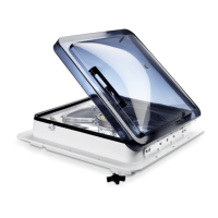
4 Model 1450 Wiring Diagram
q
3-speed Switch
y
Manual Li Knob
2
w
Black (+)
u
12 VDC Fan Motor
e
Supply Power
i
Reverse Switch
r
Supply Ground
o
Red (+)
t
Black (Ground)
2
Only on Models 1400 and 1450
u
q
y
w
a
f
d
w
(+)
(-)
C
(+)
(+)(-)
s
i
a
i
o
t
r
s
e
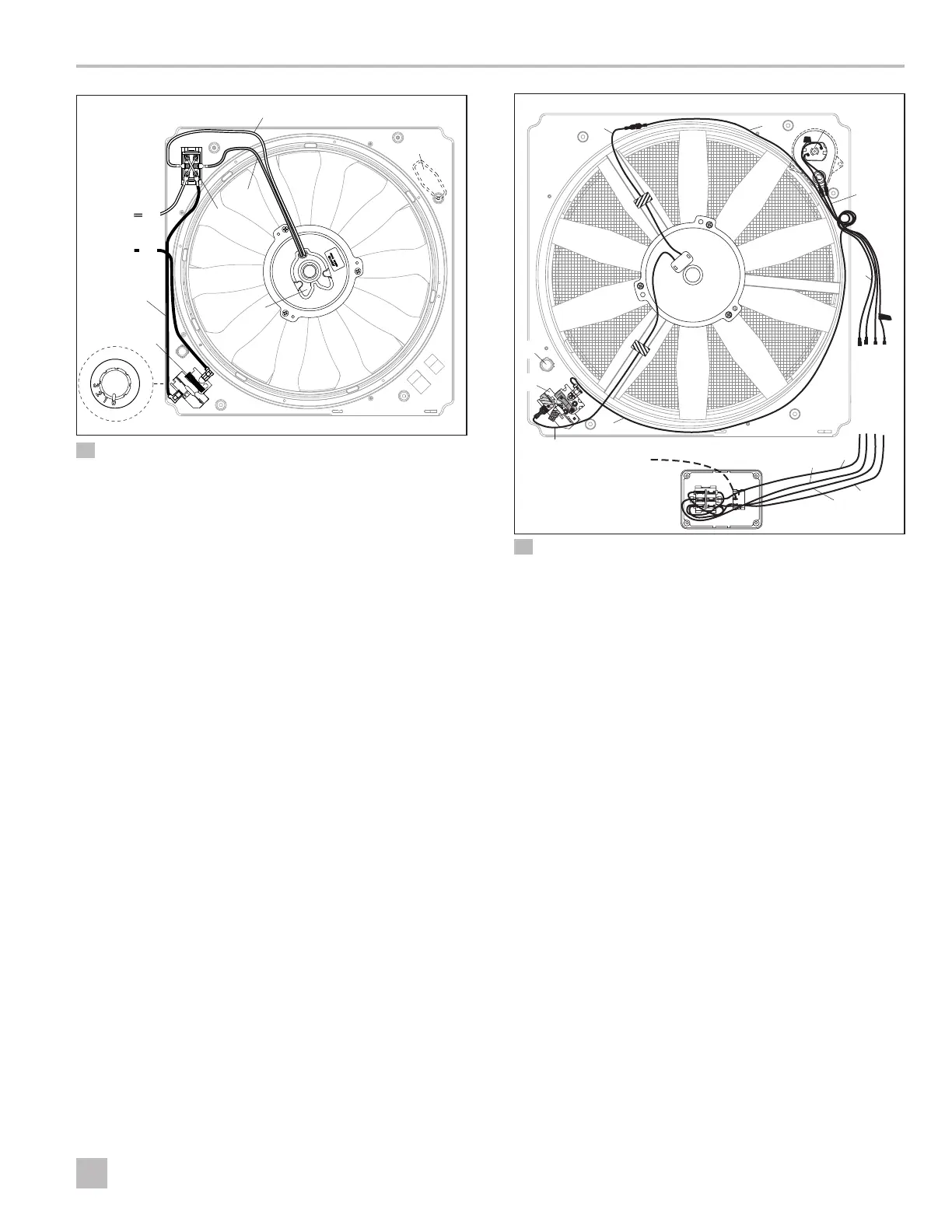
5 Model 4100 Wiring Diagram
q
#18 Black (+) Customer Supplied Lead for Wall
Control
w
#16 Black (+) 12 VDC from Wall Control to
3-speed B Terminal
e
#16 Red (+) Fan Motor to 3-speed Switch M
Terminal
r
3-speed Switch
t
Switch Plug
y
12 VDC Fan Motor
u
#16 Black (Ground) Fan to Black Fan Motor (–)
i
#16 White (–) From Wall Control to White Fan (–)
o
17 RPM Li Motor
a
#18 Red Wall Control to Black 17 RPM Li Motor
s
#18 Blue Wall Control to Red 17 RPM Li Motor
d
Location for Customer-Supplied Wire Harness
f
Wall Switch Wiring

 Loading...