9
EN
Dometic Fan Preinstallation
qq
ww
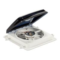
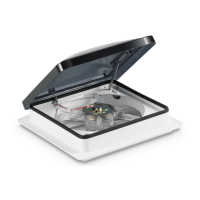
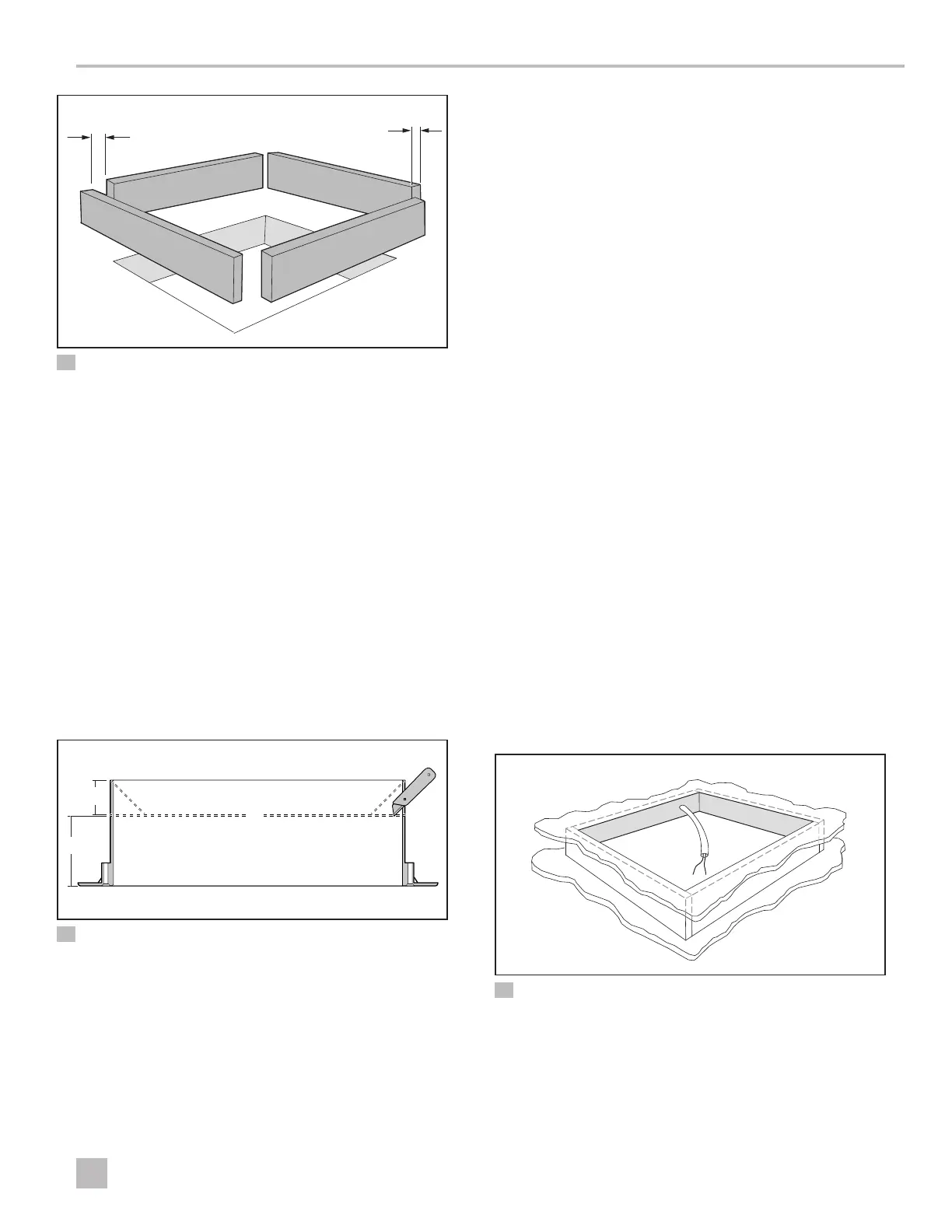
7 Frame for a Roof Opening
q
0.8 in.
(25 mm)
w
0.3 in. (6 mm) Opening for
the Power Supply Wiring
1. Build a frame for the fan opening to provide a level
platform for securing the mounting flange to the roof.
2. Leave access for the power supply wiring to pass into
the interior through the frame.
6.2 Assessing the Trim Garnish
1. Determine the length, width, and thickness or depth
of the roof or wall opening where the new fan will be
installed.
2. Confirm you have the correct trim garnish for
the depth of the opening. See “Trim Garnish
Dimensions” on page5.
w
r
q
e
8 Resizing the Trim Garnish
q
Required Trim Garnish Height
e
Garnish
w
Excess Trim Garnish to Remove
r
Score Lines
3. Use a utility knife to adjust the size of the trim garnish
to the correct height, if necessary.
a. Use a straight edge and a pen to mark horizontally
around all four sides from the top edge. Score the
marked lines.
b. Cut from the top edge of the corners at a 45
degree angle down to the score line, then
carefully break the excess plastic away from the
trim garnish.
6.3 Connecting the Power
I
If you are replacing an existing fan, use the existing
wiring only if it meets the Recreation Vehicle
Industry Association’s 16 AWG wiring and location
requirements.
This section describes how to connect the fan to a
12VDC power source.
1. Locate the nearest 12 VDC power source wiring.
2. To avoid blowing the fuse, test the power source
wiring for polarity.
a. Turn on the 12 VDC power or battery.
b. Using a multimeter, touch the red lead to the
positive source. At the same time, touch the black
lead to the neutral or negative wire.
– A correct polarity will display +12 or more volts.
– If incorrect, the multimeter will display -12 volts or
more.
c. Turn off the 12 VDC power or battery.
qq
9 Power Supply at the Roof Opening
q
6 in. (152 mm) minimum
3. Route the power source wiring to the roof or wall
opening. Add an additional 15 in. (381 mm) of wire,
to ensure an easy connection to the fan.
 Loading...