5
FIG. 9
Use an AC light bulb to test if the relays on the board
are completing a circuit. Check from the common
(white wire) to:
“NO” is a black or blue wire on the compressor relay
Terminal T1 is a black wire for high fan speed
Terminal T2 is the reversing valve on heat pumps. If
the violet wire is connected to T4 (Violet), it will oper-
ate in reverse of the mode selected.
Terminal T3 is a red wire for low fan speed
Note: Do not use a voltmeter to do these checks as
it will give erroneous readings.When the Comfort Con
trol Center is set to operate the heat pump the fan will
operate in the low speed only the Auto fan mode.
If the circuit is completed and that component is not
operating, the problem is in the wiring to the compo-
nent.
d. Dual Basement Air Conditioners and Heat Pumps
The operation of the dual air conditioner and heat pump
can be checked in the same manner as the single
basement air conditioner and heat pump. The stage
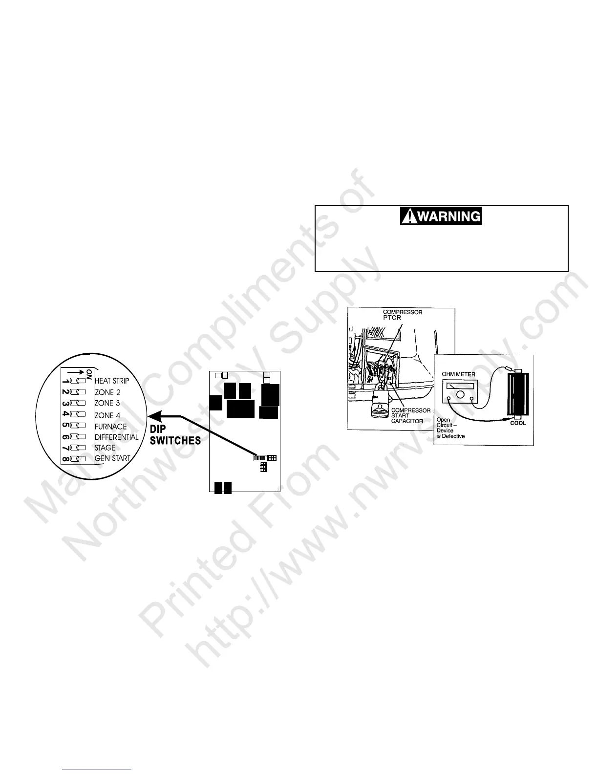
dip switch (switch 7) is turned to the “ON” position to
control the operation of the second compressor. See
FIG. 8.
Use a 115 volt AC light bulb to check from common
(white wire) to the other terminals to determine if the
circuits are being completed. If the circuit is com-
plete the light will illuminate.
Note: When the Comfort Control Center is set to op-
erate the heat pump the fan will operate in the low
speed only the Auto fan mode.
9. REVERSING VALVE
The reversing valve is the heart of a heat pump. It changes
the direction of the refrigerant flow through the coils, and
changes the system from cooling to heating.
The reversing valve’s solenoid can be energized in either the
heat or cool mode of operation. Duo-Therm roof top heat
pumps have the solenoid energized in the cool mode.
One method of checking the reversing valve is to feel the
refrigerant line at the top of the inside coil. In the COOL
mode, this line will be cool to the touch. In the heat mode
the line will be warm or hot to the touch. If you do not feel a
FIG. 8
cold line in the cooling mode, the direction of flow is not
correct.
Check the solenoid coil for ohms continuity. An open cir-
cuit (no continuity) shows the solenoid is defective and must
be replaced.
10. PTCR DEVICE
The positive temperature coefficient resistor/PTCR has re-
placed the compressor start relay and in some cases the
start capacitor. It should be checked in two different ways:
1. Check continuity. Turn “OFF” the AC power at the main
breaker and Comfort Control Center system switch. Dis-
connect the PTCR from the circuit. Using an ohmme-
ter,check for continuity through the PTCR. If there is no
continuity the PTCR is open and needs to be replaced.
This is an energized circuit. Shock can oc-
cur if not tested properly. Testing is to be
done by a qualified service technician.
2. The second check is an amp reading. Clamp an amme-
ter around the wire from the start capacitor. See FIG. 9.
Turn on the AC power and set the Comfort Control Cen-
ter to the cooling mode. When the compressor starts,
the ammeter should show a reading for approximately
one second. If there is no amperage reading or a pro
longed reading, the PTCR is faulty and must be replaced.
11. HEAT STRIP
Check the heat strip for continuity across the outside termi-
nals at the heat strip plug. If the circuit is open (no continu-
ity) the fuse link limit or heater element may be defective.
When the Comfort Control Center is set to operate the heat
strip the fan will operate in the low speed only the Auto fan
mode.
Manual Compliments of
Northwest RV Supply
Printed From
http://www.nwrvsupply.com
 Loading...