7
INSTALLATION INSTRUCTIONS
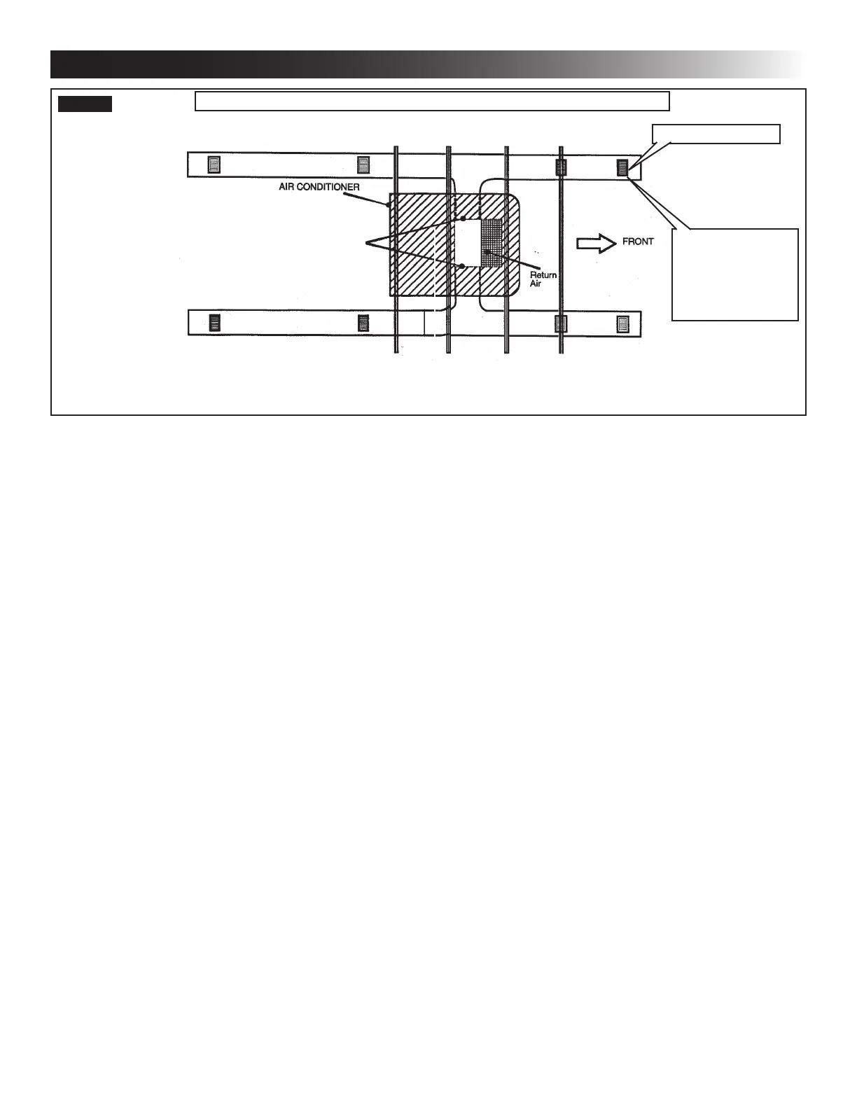
FIG. 5
Duct Size And Requirements For 3105007.XXX And 3105935.XXX RAG
Register Required
Registers
8 Min - 12 Max.
(Per Unit)
14 Sq. In. Free
Area Per Register
D. Wiring Requirements
1. Route a copper, with ground, 120 Vac supply
wire from the time delay fuse or circuit breaker
box to the roof opening. Use a listed/certied
non metallic - sheathed single strand cable. See
"A. Table - Unit Data" on page (4).
a. This supply wire must be located in the front
portion of the roof opening.
b. The power MUST be on an appropriately
sized separate time delay fuse or circuit
breaker. See "A. Table - Unit Data" on page
(4).
c. Make sure that at least 15″ of supply wire
extends into the roof opening This ensures
an easy connection at the junction box.
d. Protect the wire where it passes into the
opening with approved method.
2. Route a dedicated 12 Vdc supply wire (18-22
AWG) from the RV converter (ltered side) or
battery to the roof opening.
When a Comfort Control Center 2 (here-
in-after referred to as CCC 2) thermostat
is being installed with more than 2 zones,
route a dedicated 12 Vdc supply wire (18-
22 AGW) to zone 1 and zone 3 roof open-
ing.
a. This supply wire must be located in the front
portion of the roof opening.
b. Make sure that at least 15″ of supply wire
extends into the roof opening.
3. Thermostat Communication Cable
a. CCC 2 Thermostat
I. Route a 4 conductor communication ca-
ble from the roof opening to the thermo-
stat mounting location using the shortest
most direct route. Make sure that at least
15″ofthewireextendsintotheroofopen-
ing and 6″ extends from the wall at the
thermostat mounting location. See "E.
Choosing Thermostat Location" on page
(8).
When more than one unit is being
installed (additional zones) with the
CCC 2 thermostat, an additional
4 conductor communication cable
MUST be routed to each additional
unit roof opening. Make sure that
atleast15″ofthewireextendsinto
the roof opening. See (FIG. 27).
b. LCD SZ Thermostat
I. Route a 3 conductor communication ca-
ble, 18 to 22 AWG, from the roof open-
ing to the Liquid Crystal Display Single
Zone (hereinafter referred to a LCD SZ)
thermostat mounting location. Make sure
thatatleast15″ofthewireextendsinto
theroofopeningand6″extendsfromthe
wall at the thermostat mounting location.
See "E. Choosing Thermostat Location"
on page (8).
 Loading...