- 22 -
PERIODIC MAINTENANCE
Checking the control system
Check the control system by connecting/disconnecting the
120V AC power, starting/stopping the engine, etc.
Checking the connections
Check all connections in the LP gas system (at the 1.
back of the refrigerator) for gas leaks. The LP gas
supply must be turned on.
Apply a non-corrosive bubble solution to all LP gas 2.
connections. The appearance of bubbles indicates a
leak and should be repaired immediately!
Checking the LP gas pressure
The LP gas pressure should be checked and the main regulator
readjusted if pressure is incorrect. The correct operating pres-
sure is 11 inches of water column. Measure the LP gas pressure
at the test port, just ahead of the burner jet.
Cleaning the fl ue baffl e and burner
Inspect the fl ue baffl e. It should be reasonably clean and free
of soot. Heavy soot formation indicates improper functioning
of the burner.
To clean the fl ue and burner, follow these steps:
Turn off the refrigerator. 1.
Unplug the power cord from the 120V AC outlet. 2.
Disconnect the wires or shut off the 12V DC power
supply to the refrigerator.
Turn off the manual shut off valve.3.
Remove cover from burner housing. Remove the 4.
burner mounting screws and then, the burner as-
sembly.
Remove the wire and fl ue baffl e from the top of the 5.
fl ue tube.
Using a fl ue brush, clean the fl ue from the top. Blow-6.
ing compressed air into the fl ue will not properly
clean soot and scale out of the fl ue tube.
Put back the fl ue baffl e.7.
Clean the burner tube with a brush. Blow out the 8.
burner with compressed air.
Remove burner jet, but fi rst, clean burner area of 9.
soot and scale that fell out of fl ue tube.
Remove the burner jet. 10.
Soak the jet in wood alcohol and blow it out with 11.
compressed air.
R12. einstall and tighten the burner jet.
Reinstall the burner. Ensure the end of the burner fi ts 13.
into the slot on the burner bracket. Verify that the
slots are centered under the fl ue tube and the thermo-
couple is positioned properly (tip of thermocouple
extends over two slots of burner).
Check the electrode for proper location and gap. 14.
Turn on the manual gas shut off valve. 15.
Examine all fi ttings for leaks. (Use a commercial 16.
non-corrosive bubble solution.)
Connect the 120V power cord. Reconnect/turn on 17.
the 12V DC power.
Check the LP gas safety shut off. 18.
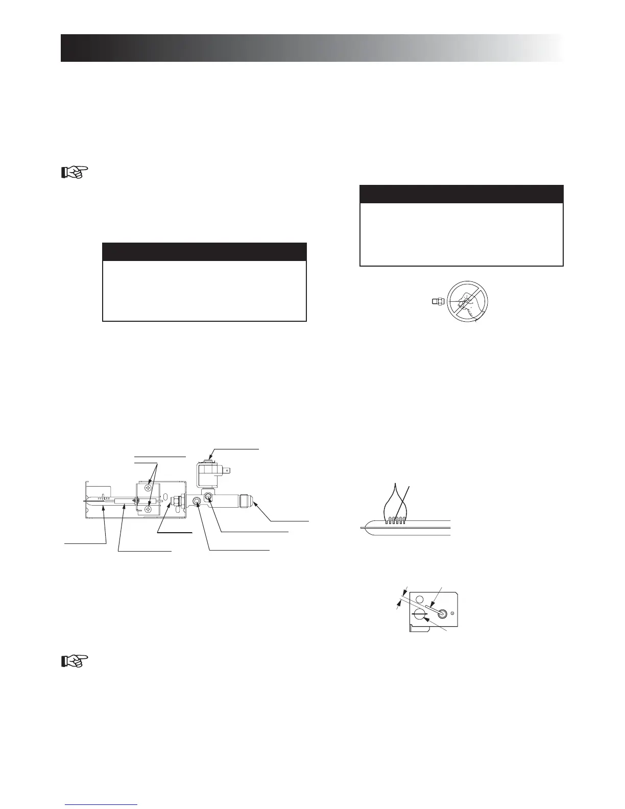
BURNER TUBE .
SPARK ELECTRODE
BURNER JET
BURNER MOUNTING
SCREWS
PRESSURE TEST PORT
MANUAL SHUT OFF VALVE
(Shown in open position)
INLET FITTING
SOLENOID VALVE
Gas equipment assembly
Electrode
Burner tube
1/8” to 3/16”
(3-5 mm)
4HEFLAMESHOULDBE
CLEARBLUEOVERTHE
SLOTSOFTHEBURNER
MAINTENANCE & SERVICE
WARNING
EXPLOSION HAZARD. Never use an
open fl ame to check for gas leaks. Failure
to heed this warning could cause an explo-
sion resulting in death or severe personal
injury.
6
!
WARNING
FIRE HAZARD. Do not use a wire or pin
when cleaning the burner jet as damage
can occur to the precision opening. Failure
to heed this warning could cause fi re result-
ing in personal injury
6
!
 Loading...