3
GENERAL INFORMATION
REQUIRED HARDWARE
(1) 3/16" x 1/2" Pop Rivet (optional - installer-supplied)
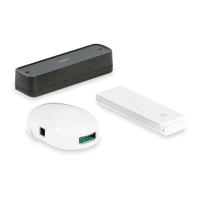
BASIC COMPONENTS
3316520.201 Wireless Receiver
• Receiver Wire Harness • Dry Contact Switch Wire Harness
• 3316518.201 Remote Control • Miscellaneous Wire Connectors
• Dry Contact Switch (Power)
OPTIONAL COMPONENTS AND KITS
3316519.205 Vibration Sensor (Black) 3316519.202 Vibration Sensor (White)
REQUIRED TOOLS
Drill Phillips Screwdriver / Bit
#11 (0.191") Drill Bit 7/16" Hex Nut Driver / Bit
Riveting Tool Needle Nose Pliers
Flat-Bladed Screwdriver / Bit (Small) Wire Cutter
A. Receiver Control Range
L1 IN THE AIR L2 WITH CONCRETE WALLS EMISSION FREQUENCY
12 V 200 m (656.17 ft) 35 m (114.83 ft) 433.92 MHz
INSTALLATION
ELECTRICAL SHOCK HAZARD. Disconnect 120 Vac power from RV. Failure to obey this warning could result
in death or serious injury.
Install a 15 A fuse (installer supplied) at fuse panel for positive (+) 12 Vdc power supply ( RED wire) to product.
Otherwise, damage to unit could occur.
Disconnect the positive (+) 12 Vdc terminal from supply battery. Otherwise, damage to unit could occur.
Disconnect power for ALL procedures under this section. Use a grommet (installer supplied) or equivalent protec-
tion when routing wire through the RV’s [roof / oor / walls].
A. Installing The Receiver
1. Determine the receiver location.
2. Route the wiring.
If using dry contact switches, route the installer-supplied wiring inside the RV from the receiver location to the dry contact
switch installation site.
 Loading...