13
5.8 LED Display Panel
With the control panel in the OFF position, check for DC
voltage at Plug 1, Terminal 4 (orange wire) positive and
terminal 5 (red wire) negative DC volts at the lower circuit
board. If no voltage to upper control, then check for input
DC volts between J1 positive and J10 negative terminals
on the lower circuit board. If no voltage into lower control
correct power supply to control system. If DC volts at J1
(positive) and J10 (negative) and no volts on orange wire
to upper control and fuse test OK, replace the lower board.
Next, with control panel in the ON position, check for DC
voltage at the upper circuit board between terminal P1-4
(orange) positive input from lower control , P1-3 (black
wire) positive output to lower control, P1-5 (green) posi-
tive output to lower control and P1-1 (red) negative and
or chassis ground. If no voltage and your previous check
veried voltage on the orange wire at the lower board the
upper display board or wire harness would be at fault.
The orange wire sends power to upper control and when
turned on the upper control sends volts back down the
green and black wire. The red wire in the harness is the
upper display ground ( 12 volt negative) .
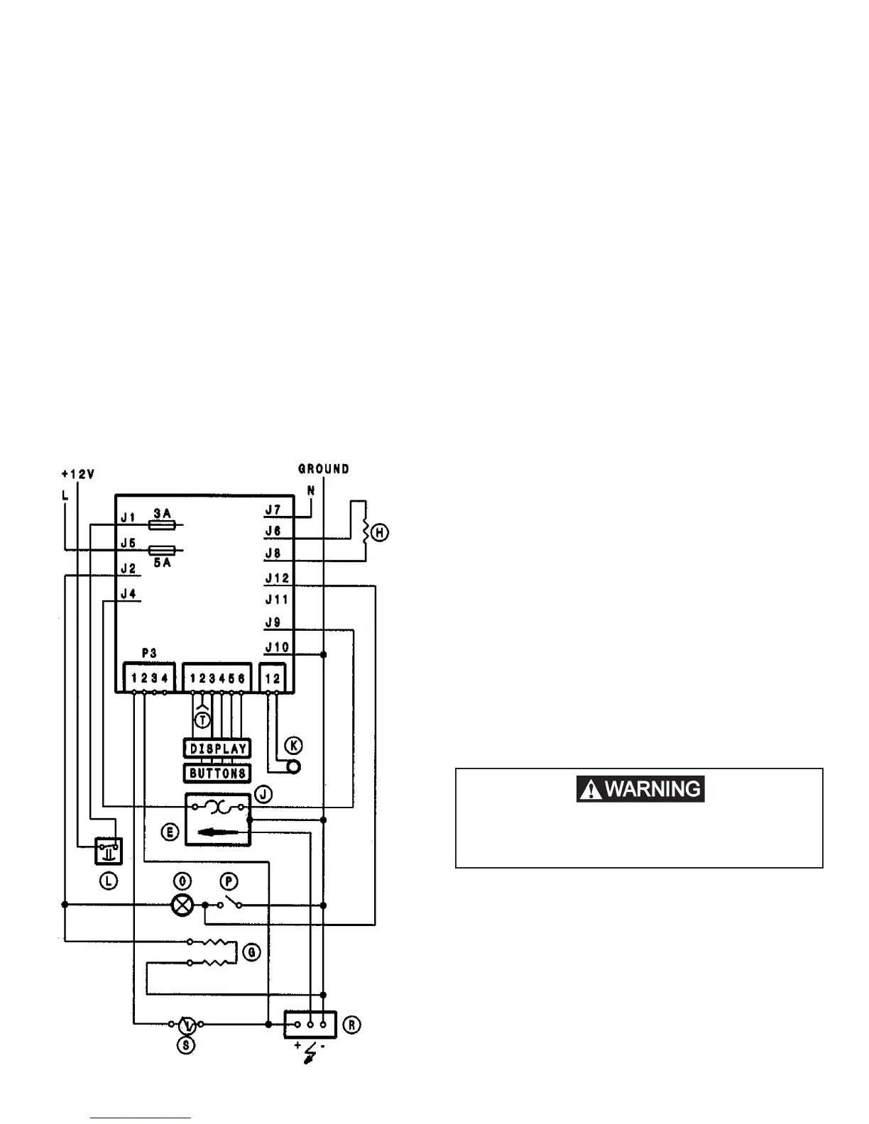
5.9 Lower Board
P1 To upper display board
P2 Thermistor
P3 To gas valve and igniter
J1 Positive 12V DC from thermofuse / terminal block
J2 To interior light
J3 To heating cable for climate control
J4 Negative lead from thermocouple
J11 Open not used on this model (TAG Line)
J12 Low ambient control
J6 AC neutral (White)
J7 AC heater
J5 AC Hot (Black)
J8 AC heater
J9 Positive wire from thermocouple
J10 Negative to Chassis ground at control board
NOTE: Terminals 9 and 10 could be reversed as both ter-
minals are chassis ground on control board.
Lower Board Testing
ALL TESTS ARE TO BE DONE WITH THE RE-
FRIGERATOR IN THE COOLING MODE.
Unplug the thermistor from the control board during
lower board testing to assure unit is calling for cool-
ing.
DC Volts
Measure volts between terminal J1 positive and J10
ground. Voltage should be the same as at the positive (+)
and negative (–) on DC input terminal block. The operat-
ing range is 9.6 min to 22 max. Refer to wiring diagram on
the product number unit you are currently working on. If
voltage outside the 9.6 to 22, check power supply, termi-
nal block and correct power source before going on with
the test.
AC Mode
Before testing the lower board for AC operation, test up-
per control board ON/OFF switches, LED display control
and wiring harness between upper and lower controls.
Next check that incoming AC voltage is present at termi-
nals J5 (black) and J6 (white) on the circuit board. With
unit in AC mode, check for voltage at the heating element
connection terminals J7 and J8 on the circuit board. If no
voltage is present and 5 amp AC fuse, 3 amp DC fuses,
wiring harness and upper controls test ok, change the
lower control board. The AC voltage detection circuit is
damaged. Reference section 11 Dianostic Mode.
This is an energized circuit. Shock can occur
if not tested properly. Testing is to be done
by a qualied service technician.
 Loading...