Supplement Paper Apollo SW 3.2n, SW 4.n 3
Chapter 3 – User Interface
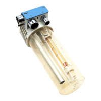
CO2 Flow Control
The CO2 flow control is located on the right side on
the Apollo, not adjacent to the other flow controls
for O2, N2O, and Air. The module can only be oper-
ated by the flow meter and the flow control knob
depicted in "The CO
2 Module" on page 2.
Turn the control knob counterclockwise to increase
the CO
2 flow and clockwise to decrease the flow.
The current flow is shown on the CO2 flow tube and
as part of the total flow on the total flow meter.
Connecting the Gas Cylinders for O2,
N
2O, CO2, and Air
The Apollo is equipped with ANSI standard pin-
indexed hanger yokes for E-size cylinders to con-
nect backup gas cylinders to the anesthesia
machine. The yoke for O
2 is standard, the yokes for
N2O and Air are optional. All cylinder yokes are
located on the back of the machine as shown in Fig-
ure 25 of the Instructions for Use.
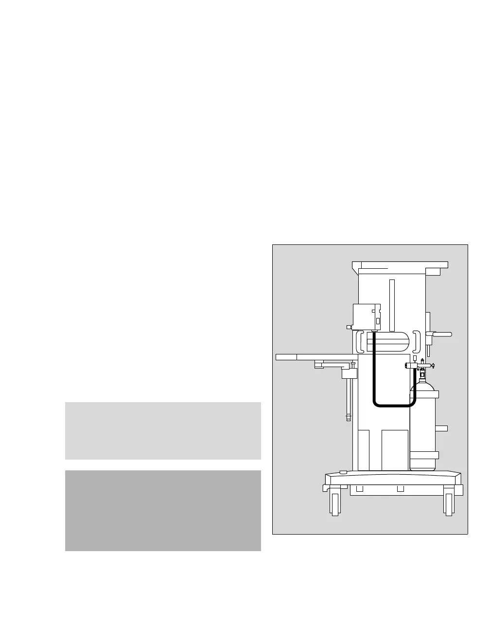
The CO
2 module requires an externally mounted
fourth gas cylinder. As shown in Figure 25a, the
position for the CO2 cylinder is on the right hand
side of the machine (as you face the machine). The
CO
2 cylinder mount is compatible with pin-indexed
E-size cylinders and the gas inlet is equipped with
a NIST gas-specific connection for the cylinder.
NOTE
The user must position the gas cylinder and the
pressure regulator in such a way that the gauge of
the pressure regulator can be read from the front
of the anesthesia machine.
CAUTION
Risk of device failure.
Compressed gas supply (central supply or cylin-
der): To avoid damaging the device(s) attached to
a gas supply, use only medical gases. Pay partic-
ular attention to national and international stan-
dards regulating the use of medical gases.
Figure 25a. CO2 cylinder location

 Loading...