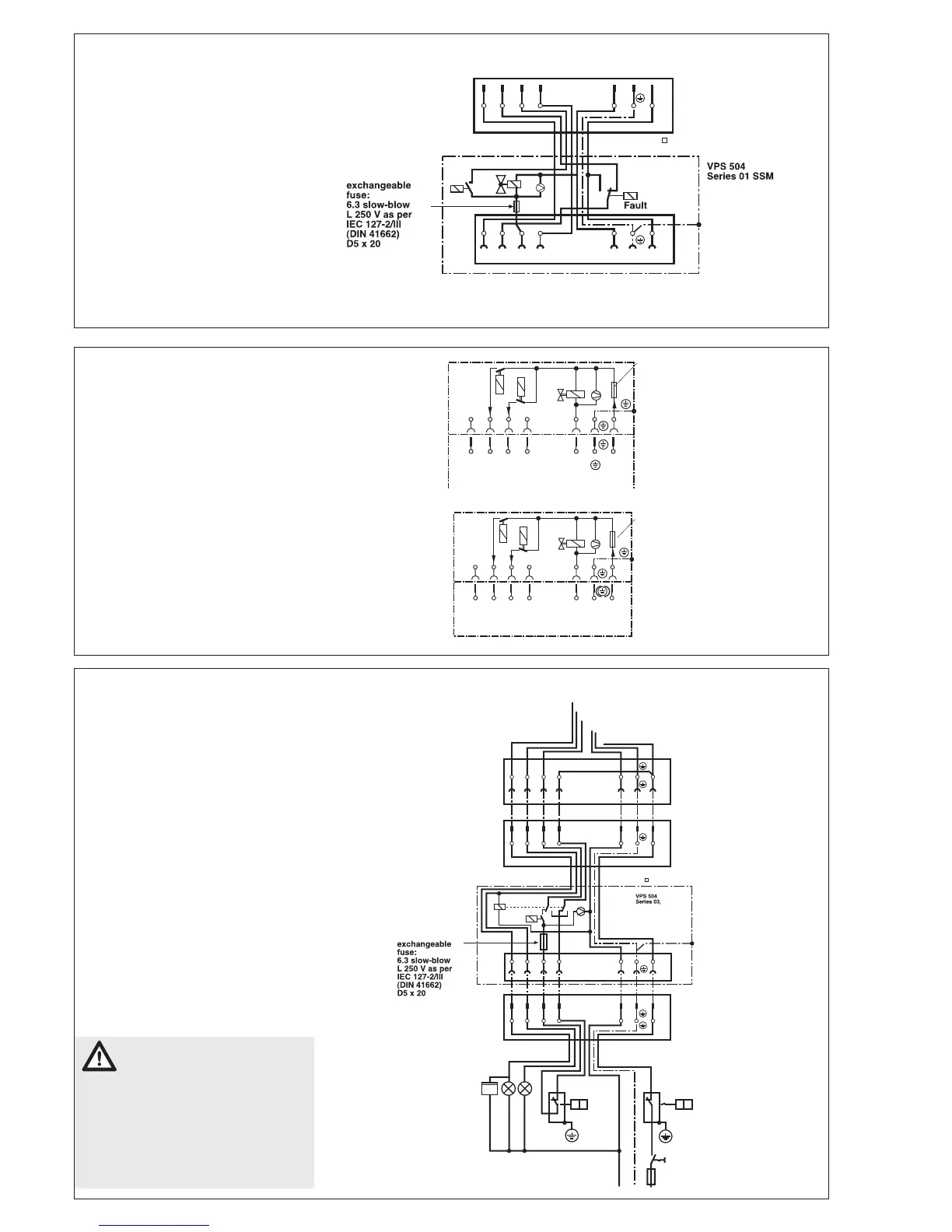
Electrical connection
VPS 504 S03
The electrical connection of VPS
504 S03 is performed as in VPS
504 S01.
Additional switching feature of
VPS 504 S03
If a fault signal is existent on S3
(burner fault), the regulator chain is
bridged to the burner via an additional
relay in VPS 504 S03 and at the same
time the operating voltage of VPS 504
S03 is interrupted.
After eliminating the burner fault, the
valve proving system is restarted.
Only the fault signal coming
from the automatic burner
control of the burner may be con-
nected to connection S3. If you
do not observe this instruction,
persons may be injured or ob-
jects may be damaged. Therefore,
strictly keep to this instruction.
Electrical connection
VPS 504 S02
The VPS 504 S01 is connected in
series between temperature regula-
tor and automatic burner control via
a 7-pole connector.
The boiler male connector is inserted into
the female connector of VPS 504.
For pin assignment of female con-
nector VPS 504 and heat generator
male connector, refer to connection
diagram.
Switching feature: No disconnection
between operating voltage circuit and
control circuit.
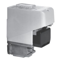
Electrical connection
VPS 504 S01 SSM
Group fault alarm
The electrical connection of VPS 504
S01 SSM is performed the same way as
with the VPS 504 S01 (see page 5).
Additional switching characteristic
of VPS 504 S01 SSM
If the test path is „untight“, the VPS
switches to fault.
An additional relay in the VPS interrupts
the burner fault line S3 between burner
and heat generator. At the same time,
voltage is applied from the heat genera-
tor to S3 line and the LED H1 lights up.
 Loading...