Table4. Programming for reverse power and additional features
Function
code Description Instructions
141 Regulator Identification FUNC, 141, ENTER, EDIT, Value, ENTER
Requirements for Reverse Sensing Mode without IDPTs
039 Source Voltage Calculation FUNC, 39, ENTER, EDIT Scroll - On; Off, ENTER
Required for Reverse Sensing Modes
051 Reverse Set Voltage FUNC, 51, ENTER, EDIT, Value, ENTER
052 Reverse Bandwidth FUNC, 52, ENTER, EDIT, Value, ENTER
053 Reverse Time Delay FUNC, 53, ENTER, EDIT, Value, ENTER
054 Reverse Line Drop Comp. Resistance FUNC, 54, ENTER, EDIT, Value, ENTER
055 Reverse Line Drop Comp. Reactance FUNC, 55, ENTER, EDIT, Value, ENTER
056 Reverse Sensing Mode FUNC, 56, ENTER, EDIT, Scroll - Locked Forward; Locked Reverse; Reverse Idle;
Bi-directional; Neutral Idle; Co-generation; React Bi-directional, BiasBi-directional,
Bias Co-generation; Reverse Co-generation, ENTER
Required for Voltage Reduction Mode
070 Voltage Reduction Mode FUNC, 70, ENTER, EDIT, Scroll - Off; Local/Digital Remote; Remote/Latch; Remote/Pulse,
ENTER
072 Local/Digital Reduction Value FUNC, 72, ENTER, EDIT, Value, ENTER
073 Remote #1 Value FUNC, 73, ENTER, EDIT, Value, ENTER
074 Remote #2 Value FUNC, 74, ENTER, EDIT, Value, ENTER
075 Remote #3 Value FUNC, 75, ENTER, EDIT, Value, ENTER
076 # of Pulse Reduction Steps FUNC, 76, ENTER, EDIT, Value, ENTER
077 % of Voltage Red Per Pulse Step FUNC, 77, ENTER, EDIT, Value, ENTER
Required for Voltage Limit Mode
080 Voltage Limit Mode FUNC, 80, ENTER, EDIT, Scroll - Off; High Limit Only; High/Low Limits, IVVC High Limit Only,
IVVC High/Low Limit, ENTER
081 High Voltage Limit FUNC, 81 ENTER, EDIT, Value, ENTER
082 Low Voltage Limit FUNC, 82, ENTER, EDIT, Value, ENTER
Multi-phase programming
When programming a control for multi-phase operation,
there are a number of setting that configure the control
for operation and a number that configure the control
to function with the connected voltage regulators. It is
important to identify the pertinent settings applying to the
individual regulators and to the control and enter them
correctly. Refer to Section6: Control Features: Multi-
phase voltage regulation and document MZ225003EN
CL-7 Multi-phase Control Reference for guidance on
programming the control for multi-phase operation.
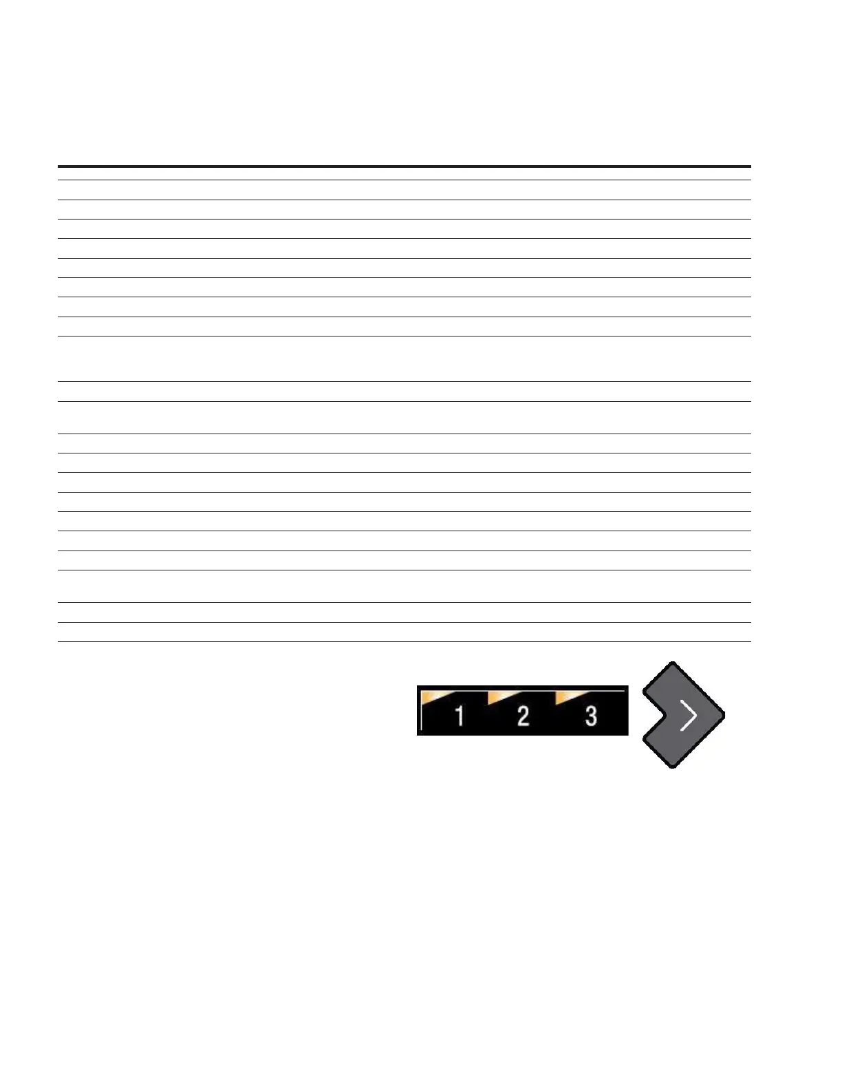
All of the basic control and regulator operational information
in this manual applies to controls and regulators whether
they are in a single- or multi-phase configuration. When
in the multi-phase configuration, the multi-phase LEDs
(marked 1, 2 and 3), see Figure13, can be used to identify
to which of the regulators the parameters apply. When
programming the multi-phase control, pay attention to the
LEDs to insure that the parameters are being entered for
the correct regulator. Pressing the forward arrow will cycle
the display through each of the connected regulators.
Figure13. Multi-phase LEDs and forward arrow
20
INSTALLATION, OPERATION, AND MAINTENANCE INSTRUCTIONS MN225003EN April 2018
CL-7 Voltage Regulator Control
 Loading...


