5EATON Dual Path Mobile Pump E-PUPI-TM005-E2 September 2007
Control Assembly -
Rear
SA – Solenoid Control -
12 Volt with Non-Contact
Feedback Sensor
SB – Solenoid Control -
12 Volt with Redundant
Non-Contact Feedback Sensor
SC – Solenoid Control -
12 Volt
HA – Hydraulic Remote -
Non Feedback, 5-15 bar
[72-217 lbf/in2] Pilot Pressure
MA – Manual Control,
Wide Band Neutral
MB – Manual Control, Standard
MC – Manual Control, High Gain
MD – Manual Control,
Wide Band Neutral, Neutral
Lockout switch
ME – Manual Control, Standard,
Neutral Lockout switch
MF – Manual Control, High
Gain, Neutral Lockout Switch
Destroke Valve - Front
0 – Not required
1 – Destroke With 12 VDC
Coil & Weather Pack
Connector
2 – Destroke With 24 VDC
Coil & Weather Pack
Connector
3 – 12 VDC Coil & DIN 43650-
A Connector
4 – Destroke with 24 VDC Coil
& DIN 43650-A Connector
Control Supply
Orifice (p) - Front
0 – No control, supply orifice
B – Diameter 0.71 [.028]
C – Diameter 0.91 [.036]
D – Diameter 1.12 [.044]
E – Diameter 1.32 [.052]
Control Servo Orifice
(s1 and s2) - Front
0 – No control, servo orifice
B – Diameter 0.71 [.028]
C – Diameter 0.91 [.036]
D – Diameter 1.12 [.044]
E – Diameter 1.32 [.052]
Special Control Options -
Front
0 – No Special Control
Options
1 – Manual Control Lever
Destroke Valve - Rear
Ref Position 23 for options
Control Supply
Orifice (p) - Rear
Ref Position 24 for options
Control Servo Orifice
(s1 and s2) - Rear
Ref Position 25 for options
Special Control Options -
Rear
0 – No Special Control
Options
1 – Manual Control Lever
2 – Control Pressure EPRV
Valve 12 VDC, Deutsch, -4
SAE O-ring Port
Main Ports (A and B)
A – 4X 1.3125-12 UN-2B SAE
O-Ring Ports; Same Side,
Right
B – 4X 1.3125-12 UN-2B SAE
O-Ring Ports; Same Side, Left
C – 4X 1.3125-12 UN-2B SAE
O-Ring Ports; Opposite Side
D – 4X -16 STC TYPE II+
Direct Port; Same Side, Right
E – 4X -16 STC TYPE II+
Direct Port; Same Side, Left
F – 4X -16 STC TYPE II+
Direct Port; Opposite Side
Drain Port Size and
Location - Front
0 – No Drain Port
1 – 1.0625 -12 UN-2B SAE
O-Ring Port - Left (D1)
2 – 1.0625 -12 UN-2B SAE
O-Ring Port - Right (D2)
3 – 1.0625 -12 UN-2B SAE
O-Ring Port - Left (D1) and
Right (D2)
4 – 1.0625 -12 UN-2B SAE
O-Ring Port - Left (D1) and
Right (D2), Left Side Plugged
5 – 1.0625 -12 UN-2B SAE
O-Ring Port - Left (D1) and
Right (D2), Right Side Plugged
Drain Port Size and
Location - Rear
0 – No Drain Port
1 – 1.0625 -12 UN-2B SAE
O-Ring Port - Left (D3)
2 – 1.0625 -12 UN-2B SAE
O-Ring Port - Right (D4)
3 – 1.0625 -12 UN-2B SAE
O-Ring Port - Left (D3) and
Right (D4)
4 – 1.0625 -12 UN-2B SAE
O-Ring Port - Left (D3) and
Right (D4), Left Side Plugged
5 – 1.0625 -12 UN-2B SAE
O-Ring Port - Left (D3) and
Right (D4), Right Side Plugged
Auxiliary Port
0 – No Auxiliary Port
A – .750-16 UNF-2B SAE
O-Ring Port - Left (C1) and
Right (C2), Left Side Plugged
B – .750-16 UNF-2B SAE
O-Ring Port - Left (C1) and
Right (C2), Right Side Plugged
C – .750-16 UNF-2B SAE
O-Ring Port - Left (C1) and
Right (C2)
D – .750-16 UNF-2B SAE
O-Ring Port - Left (C1) and
Right (C2), Left Side Plugged,
Remote Filter, Return from
Filter to Charge Port Required
(#34 continues next column)
(continued from previous column)
E – .750-16 UNF-2B SAE
O-Ring Port - Left (C1) and
Right (C2), Right Side Plugged,
Remote Filter, Return from
Filter to Charge Port Required
Bypass Valve
0 – No Bypass Valve
A – With Bypass Valve
Sensor Options
0 – No Sensor
A – Magnetic Speed Sensor
Shaft Seal
A – Polyacrylate
B – Nitrile
C – Viton
Special Features
00 – No Special Features
AA – Diagnostic Ports - Front
Pump 2X .3125-24 SAE O-ring
Ports (s1 & s2), Rear Pump
2X .3125-24 SAE O-ring Ports
(s1 & s2)
AB – Externally Adjustable
Displacement Limiters
AC – Diagnostic Ports - Front
Pump 2X .3125-24 SAE O-ring
Ports (s1 & s2), Rear Pump
2X .3125-24 SAE O-ring Ports
(s1 & s2), Externally
Adjustable Displacement
Limiters
Paint
0A – Primer Red
0B – Primer Black
CD – Primer Blue
Identification
A – Standard
Design Code
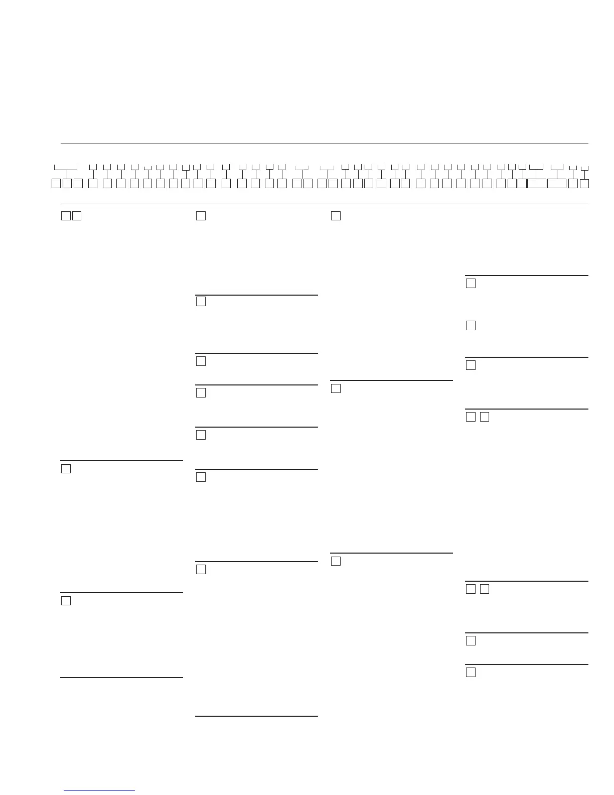
A –
21 22
23
36
24
43
42
4140
3938
37
35
34
33
32
31
30
29
28
27
26
25
AED * * * * A * * * * * * * * * * ** ** * * * 0 * * * * * * * * * * * ** ** A A
1 2 3 4 5 6 7 8 9 10 11 12 13 14 15 16 17 18 19 20 21 22 23 24 25 26 27 28 29 30 31 32 33 34 35
38,39 40,41 42
43
Model Code
36 37
 Loading...